With plenty of USB-powered devices available today, a portable power source that can deliver the same voltage and current of a standard USB port is always a nice addition to our tool set.
Here we will design a simple USB Power Bank based on the standard tool handle created in the Projects section (“Lithium-ion Batteries Safety and Tool Design”).
Specifications
A USB Power Bank must be capable of:
- Delivering power at the USB standard voltage (5 V).
- Delivering current that is useful for practical purposes (1 A to 2 A).
- Storing a reasonable amount of energy.
- Being recharged using a USB connection.
Our standard tool handle can deliver current in excess of 2 A (protection circuit will cut at 3 A), store a good amount of energy (depending on the battery, it could go as high as 3,500 mAh), and can be recharged via a micro USB port.
However, it can only deliver around 3.7 V (nominal voltage, the full battery range is 2.5 V to 4.2 V); we need to find a way to increase and regulate the voltage at a fixed 5 V.
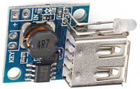
These are called “voltage step-up converters”, and their function is to take a low voltage at the input and deliver a higher value at the output, with feedback circuits to keep the output steady. There are several step-up modules available; we will be using one that is perfect for our application (Figure 1).
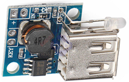
FIGURE 1.– USB 2.6 to 5 V, 2 A step-up module
This module has several useful features:
- Accepts inputs from 2.6 to 5.5 V and delivers 5 V at the output, with a standard USB socket.
- Can deliver current up to 2 A, with up to 93% conversion efficiency.
- Includes a red/green LED indicator, the red lights up when the input goes lower than 3.6V.
- It has over-current and over-temperature protection.
Building the unit
The whole process is as simple as connecting the standard tool handle to the input of the step-up converter, and the USB Power Bank is ready! (Figure 2).
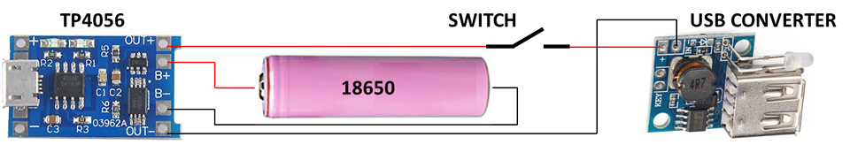
FIGURE 2.– USB Power Bank electric diagram
Just make sure to connect the positive wire from the handle to the + IN tab in the module, and the negative to the – IN. There are other 2 tabs (named KEY) where you could eventually connect an ON/OFF switch; those pads come connected by a 0 Ω resistor, so we will leave them untouched. We have our own ON/OFF switch already mounted in the handle.
The only missing part now is to have an appropriate 3D printed enclosure that connects with the handle on one end, and exposes the USB port and the LED on the other (Figure 3).
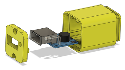
FIGURE 3.– 3D printed parts and board mount
The module fits securely with rails in the main body, and the front cover is attached with 2 screws. The body gets firmly connected to the tool handle by the groove in the back end (Figure 4).
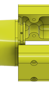
FIGURE 4.– Grooves in the tool head match protuberances in the handle to create a secure union
Required parts
Only a few parts are required to create this tool head; all of them are widely available as of July 2020; the links are just for reference, you may find them somewhere else.
- Step-up USB voltage converter.
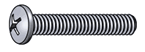
- Screws:
- Philips Pan Head #2-56 x 3/8 (quantity: 2).
- 3D printed parts (STL files included in the Download section):
- Head main body.
- Front cover.
- Miscellaneous:
- Wires (stranded, 22-24 AWG).
- Soldering iron and solder.
Printing the parts
The main head body may be printed vertically (on its back end) using supports; the front cover can be printed on its flat face without supports, or on the opposite face (for esthetic reasons) but using supports. A layer height of 0.2 mm is adequate with no other special considerations.
Actual tool pictures
This is how the USB Power Bank looks like (Figures 5 and 6). The front shows the USB socket and the indicator LED. The rest of the body is the same reviewed in the previously referred article (“Lithium-ion Batteries Safety and Tool Design”).
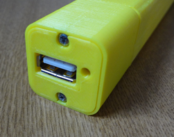
FIGURE 5.– Front face of the USB Power Bank
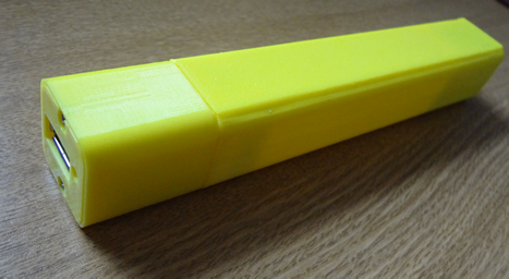
FIGURE 6.– Full tool