Lithium-ion batteries have become the energy storage technology of choice for diverse applications, from portable phones to electric vehicles. Their high energy density characteristics made them the ideal choice, balancing light weight with increased capacity, compared to other existing technologies.
These batteries come in various formats, the two most common are flat and cylindrical. Their popularity has increased to the point that many do-it-yourself projects will include them nowadays.
But, with all the advantages comes a notable disadvantage: they are dangerous if not used properly. These batteries may catch fire, or even explode, if they are overcharged (overvoltage) or short-circuited (overcurrent). In addition, they may be damaged if they are discharged beyond a certain threshold (over-discharged).
Here we will review a proper way to use Lithium-ion batteries so they can be incorporated into your next project safely, and a practical application for do-it-yourself tools.
Basic safety requirements
There are basically three keywords to consider when dealing with Lithium-ion batteries safety:
- Overvoltage (risk of fire or explosion).
- Overcurrent (risk of fire or explosion).
- Over-discharge (risk of damage).
Essentially, no Lithium-ion battery should be used without a proper protection circuit monitoring these variables. Ideally, this circuit should be able to monitor and control the voltage and current while charging as well as during discharge.
The simplified charging process has 2 phases, constant current until reaching the maximum voltage, and then constant voltage, while the current drops down to almost zero. During this process, the charging circuit limits the maximum current during the initial phase as well as the maximum voltage during the final one. In addition, it senses the current decrease and cuts the process once a certain low level has been reached, to avoid overcharging.
During the discharge process, when a load is connected to the battery, the control circuit monitors the current and voltage; if either the current exceeds the maximum allowed value, or the voltage goes below the lower threshold, the circuit disconnects the load, preventing a damaging situation.
We could design such a circuit, but there is no need to do so; these batteries are so popular now that there are very inexpensive solutions already available in the market. One of such solutions is the TP4056 module (Figure 1).
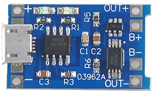
FIGURE 1.– TP4056 Lithium-ion battery charger/protector module
The TP4056 module takes care of all the safety measures we described before, during charging and discharging.
A quick note here: earlier versions of this module did not include discharge protection, only charge control. You can identify them by the shorter board and the lack of “OUT” terminals (Figure 2).
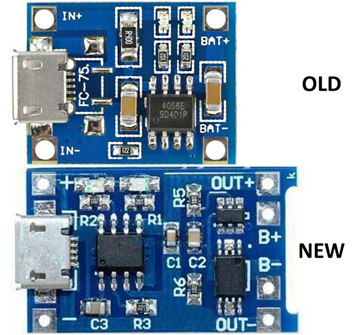
FIGURE 2.– Old and new TP4056 module versions
Both include the TP4056 charge control chip, as well as the micro USB input. The difference is that the new board has a current/voltage monitor circuit and a double MOSFET to disconnect the load when a situation of overcurrent or under-voltage is detected. The board is longer to accommodate these 2 additional chips, and there are 4 terminals: B+ and B- to connect the battery, OUT+ and OUT- to connect the load.
The main characteristics of this module can be summarized here:
- Input voltage: 4.5 – 5.5 V (micro USB connector and circuit tabs).
- Full charge voltage: 4.2 V.
- Charging current: 1 A (adjustable via R3).
- Charge indicator (LEDs): charging RED; charged BLUE.
- Maximum discharge current: 3 A.
- Minimum discharge voltage: 2.5 V.
This module is adequate for all Lithium-ion batteries with a nominal voltage of 3.6/3.7 V and charge voltage of 4.2 V. The charging current can be configured to a lower value by changing R3, called RPROG. The equation to calculate the current is:
![]()
ICHG is the charging current. Substituting with a few values of RPROG we can construct a table (which is usually listed in the TP4056 chip datasheet):
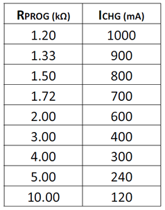
The board usually comes with a 1.2 kΩ resistor, so it is programmed to deliver 1 A (Figure 3).
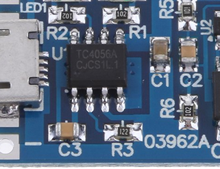
FIGURE 3.– Charge current programming resistor (R3) has a value of 1.2 kΩ (122)
Regarding the input port, there are even newer versions that come with a USB C connector; just make sure you buy the right one depending on your actual needs.
Finally, this device has NO reverse polarity protection in the output; make sure you connect the battery correctly otherwise the output will be damaged permanently.
Connecting the battery and the load
The output connections are normally printed in the circuit board:
- B+: to positive terminal of the battery.
- B-: to negative terminal of the battery.
- OUT+: to positive side of the load.
- OUT-: to negative side of the load.
Figure 4 shows the basic configuration.
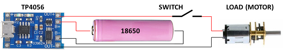
FIGURE 4.– Connecting the TP4056 to the battery and the load
The battery shown here is one of the common formats, the cylindrical 18650 type. The name comes from the dimensions, 18 mm diameter and 65 mm length (true for unprotected cells, the protected ones are slightly larger).
The battery is connected to B+ and B-, while the load goes to OUT+ and OUT-. You may have noticed that I added a switch in the circuit; this is needed to have control of the load. With no switch, the load would be always connected, thus consuming the battery charge. This might be desired in some applications, but keep in mind that the load connected during the charge process may interfere with the current sensing capabilities of the TP4056 and the charge may never end, risking overcharging the battery. Therefore, it is always recommended to disconnect the load when charging the battery; the switch will be useful for this.
A close observation of the TP4056 output pins will show that B+ and OUT+ are physically connected (same copper track); however, B- and OUT- are not. Once the battery is connected, the voltage is sensed and, if above the minimum value (2.5 V), the MOSFET connecting B- and OUT- will start conducing electricity, thus feeding the load. If the current is higher than the maximum value (3 A), the load will be disconnected. So always make sure that you respect the connections to have your circuit protected.
In some special circumstances you may want to avoid the protection circuit; for example if you are using a protected battery with a higher current rate (e.g. 8 A), and your load requires such a high current. If you keep the TP4056 protection, the circuit will cut at 3 A, and the load will not receive energy. ONLY in this case, when you are using a protected battery, you should connect both the battery and the load to B-, thus bypassing the protection circuit.
Practical application: standard tool handle
Several portable tools can benefit from having a Lithium-ion battery as the power source; it has high charge capacity and can be recharged using a standard USB port if connected to the TP4056. So we can design (and build) a few tools that can share the same standard handle, which will house the TP4056, the switch and the battery; the load will vary with the application.
Figure 5 helps visualize this concept.
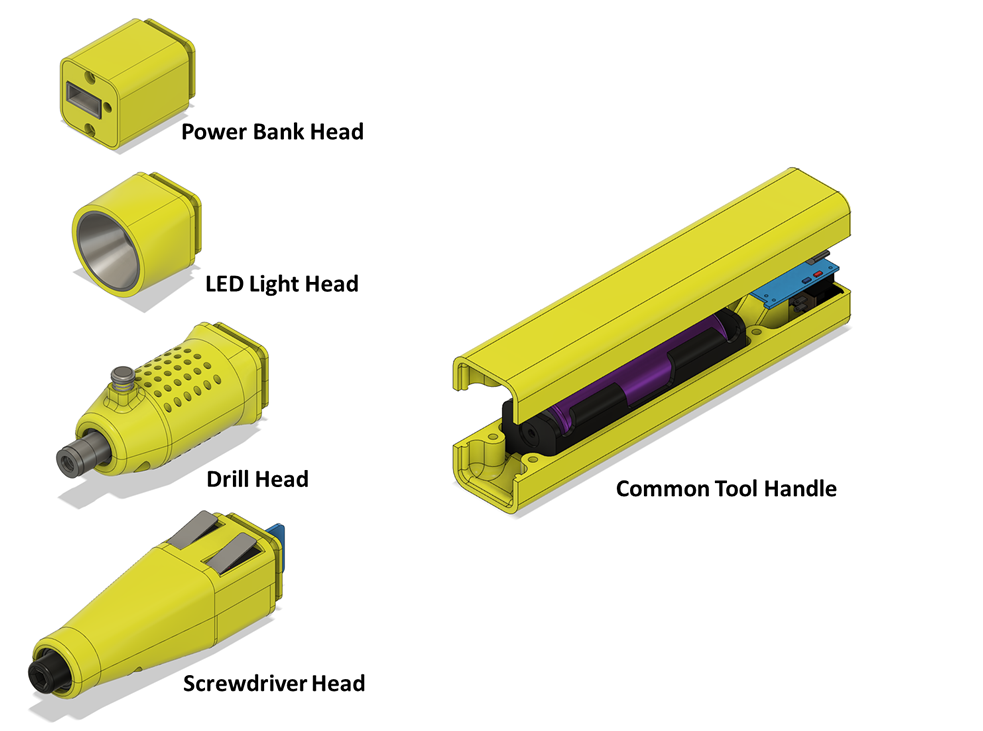
FIGURE 5.– Standard electric tool handle concept; the same power source can become several tools by changing the head
The different tool heads will be explained in separate documents (check the Tools section); let’s see now how to design the handle.
The electrical diagram is shown in Figure 6; the unconnected wires will go to the load (head).
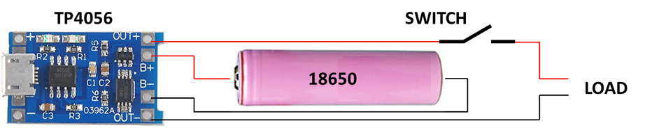
FIGURE 6.– Standard handle electric diagram
These components will be housed in a 3D printed prism, built in two halves. The rear end will accommodate the switch and the USB port of the TP4056, while the front end is shaped to make a perfect fit with each of the different heads. The battery will be placed in a standard 18650 holder for easy removal if required (it can be soldered in place, but I opted for a more general approach). Figure 7 shows the components placement.
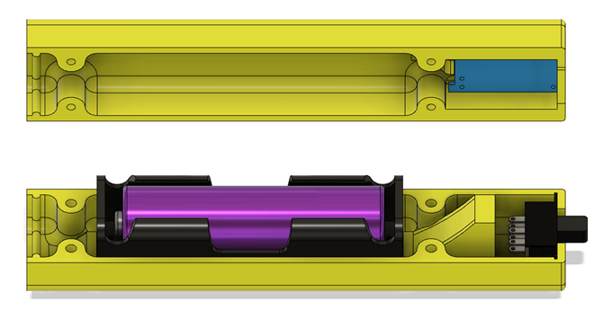
FIGURE 7.– The lower half will have the battery (in the holder) and the switch; the TP4056 is in the upper half
The components are wired following the electric diagram; they will fit in place with no screws or glue, provided the size is the same I used (see the references below). When the two halves are screwed together, the components will be held securely in place.
Required parts
All parts are widely available as of July 2020; the links are just for reference, you may find them somewhere else.
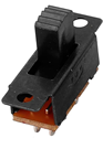
- Slide switch (DPDT) with 2 positions and 6 terminals.
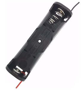
- 18650 battery holder.

- Lithium-ion battery charger/protector module TP4056.
- Screws:
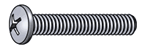
- Philips Pan Head #2-56 x 3/4 (quantity: 4).

- Battery: 18650 (button top, protected or unprotected).
- 3D printed parts (STL files included in the Download section):
- Body (top and bottom covers).
- Miscellaneous:
- Wires (stranded, 22-24 AWG).
- Soldering iron and solder.
Printing the parts
All parts can be printed with no supports if properly placed on a flat face. A layer height of 0.2 mm is adequate with no other special considerations.
Actual tool pictures
Here are some pictures from one of the tools (the LED flashlight).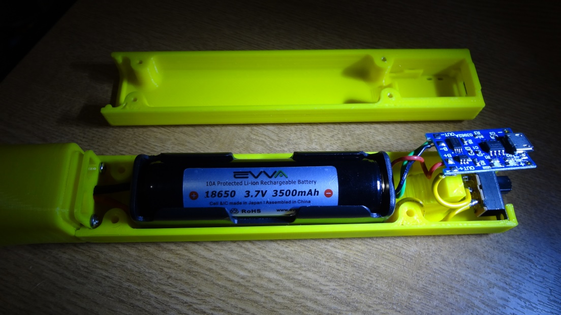
FIGURE 8.– All components mounted and wired
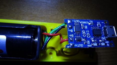
FIGURE 9.– Red and black wires go to the battery holder, while yellow and green to the load
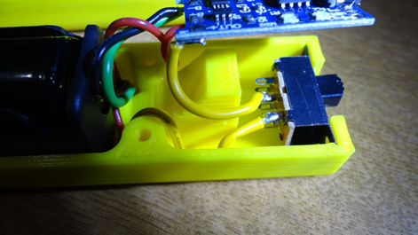
FIGURE 10.– The yellow wire reaches the switch first, before continuing to the load
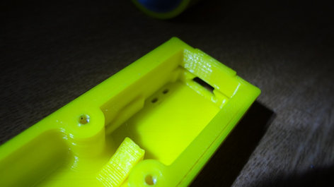
FIGURE 11.– The TP4056 module fits in grooves in the upper half; two recessed rectangles let the charging LEDs to be seen
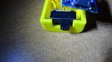
FIGURE 12.– The switch slides into grooves in the lower half
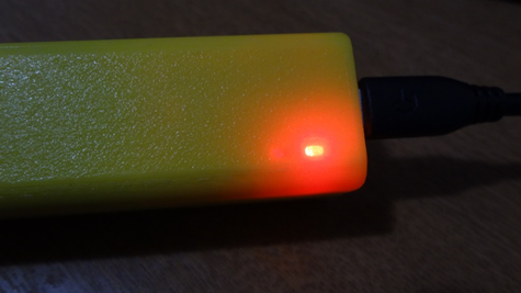
FIGURE 13.– The charging LEDs can be easily seen from outside
This is just an example of how you can use Lithium-ion batteries safely, by not exposing them to situations that may end up in fire, explosions or just damaging the battery. We have reviewed the case of a single battery, which is quite common; more elaborate designs will use 2 or more cells, in series or parallel, with the help of Battery Management Systems (BMS). This is beyond the scope of this basic tutorial, but you may explore those options if you require them; there are modules available for most configurations.
And to conclude, here is a preview of some the tools that can be made using this standard handle as the power unit.
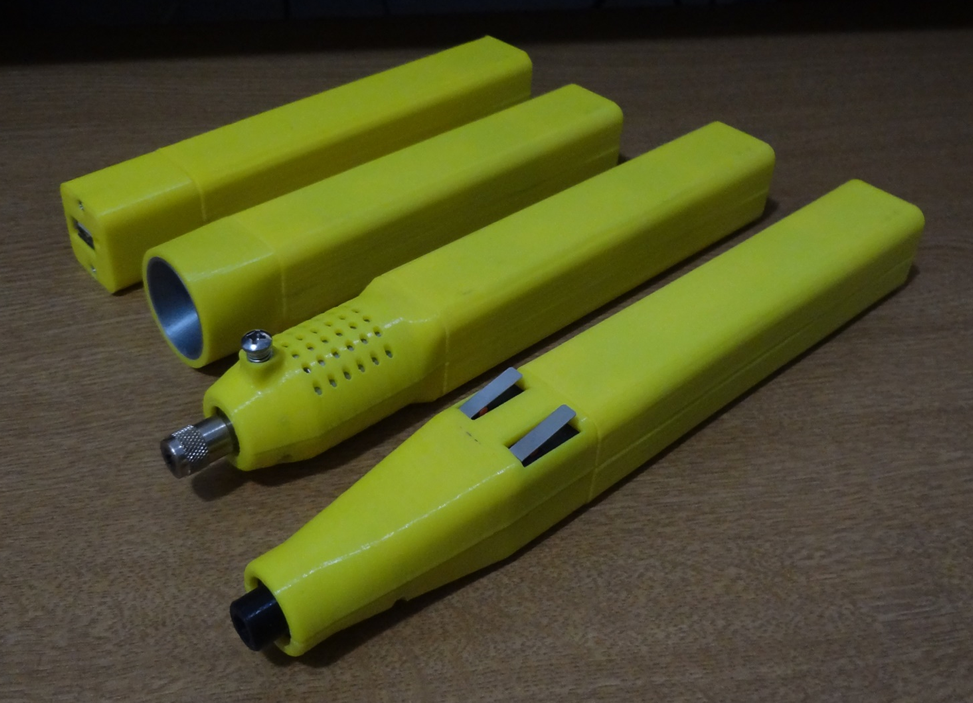
FIGURE 14.– Various possibilities using the standard handle as the power unit