The power supply is an essential element of any electronic design. However, many times it is taken for granted, and the focus is put mainly on the design specifications in terms of functionality and performance of the main circuit. A clean, well-regulated power supply may be the difference between a working circuit and a complete failure, with electrical noise running through the power wires. Here I will present a simple approach to have a clean, regulated, variable power supply to be used with any design during the testing phase in a breadboard or prototype PCB, with the added advantage of being portable and capable of delivering a good amount of power.
There are various methods for designing a regulated power supply, however they may be grouped in two main categories: Linear and Switched. The linear power supply is cleaner since there are no switching components to generate electrical noise, but at the same time the efficiency is not ideal, and there is a lot of power dissipated as heat. The switched supply is much more efficient, but the switching noise may be a drawback for use in sensitive circuits. Here we will be focused more in obtaining a very clean supply, and not much emphasis will be put on efficiency. Therefore, we will be designing a regulated linear power supply.
Regulated linear power supply
The basic building blocks for a regulated linear power supply are shown in Figure 1.
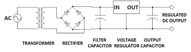
FIGURE 1.- Linear regulated power supply
The AC voltage is adjusted to the desired manageable level by the transformer and then converted into positive pulses by the full-wave rectifier. The filter capacitor eliminates most of the remaining oscillation (called ripple) and the regulator provides a clean, regulated voltage at the output. The output capacitor contributes to further stabilize this voltage.
The result is a well-regulated and clean power supply. There is still one potential source of noise, particularly when working with high current. In this case the filter capacitor may not be able to suppress the ripple and this oscillation may go through the regulator, impacting the output. A bigger capacitor may reduce the impact, but this means larger footprint and additional cost.
There is a way to completely eliminate the ripple, thus the electrical noise: using a DC supply at the input. Figure 2 shows the new design.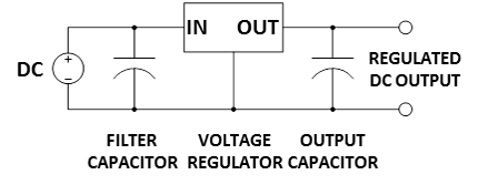
FIGURE 2.- Linear regulated power supply with DC input
A very efficient DC power supply is a battery, particularly the rechargeable type. One battery that is widely available, easy to recharge, and that can provide a reasonable current is the SLA (Sealed Lead Acid), in particular the type used for home alarm systems (Figure 3).
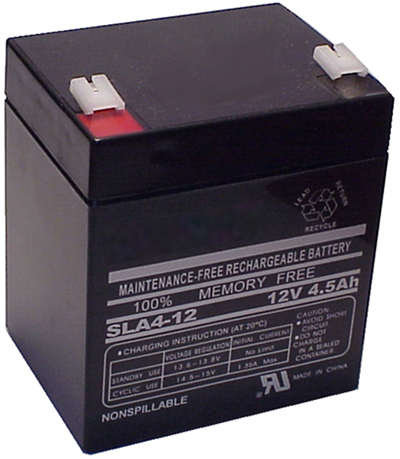
FIGURE 3.- 12 V SLA battery; the capacity is 4.5 Ah
The battery shown can deliver a nominal 12 V, and has a capacity of 4.5 Ah. This means that the battery will keep delivering the rated voltage during 1 hour if the current consumption is 4.5 A. If we consider a typical electronic circuit, mounted in a breadboard, the average consumption will be between 50 and 250 mA. Even at the worst case, 250 mA, this battery will provide 18 hours of continued power. At an average use of 2.5 hours a day, one charge will last for over a week. Additionally, the charging process is quite simple, constant current first until the maximum voltage is reached (around 14.5 V), and then constant voltage until 1/10 of the maximum charging current is flowing. However, there is no need to worry about this, since there are plenty of chargers available for purchase on the web, at very reasonable price (as an advice, please avoid the very cheap ones, which may damage the battery; always read the users’ reviews first!).
An added advantage of using a battery is the portability of the power supply; while the battery is relatively heavy, it still can be moved with the circuit to places where there is no power outlet available.
Power supply design
Our design will use an adjustable linear regulator, so the user can vary the voltage at will within the set limits, and will have a clear indication of the selected voltage. Also the current capability of the regulator will allow a wide range before reaching its limits. Here are the most relevant specifications of the design:
- Very low noise linear regulated power supply.
- Variable output voltage, from 1.25 V to 6.50 V.
- Large current capability, up to 5 A.
- Digital indication of output and input voltage.
With these specifications in mind, the proposed design is shown in Figure 4.
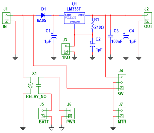
FIGURE 4.- Power supply circuit schematics
This diagram may seem confusing at first, but it is really quite straightforward once the main components are explained. The actual power supply is the top portion, from J1 to J2; the lower part is related to the digital voltmeter included to show the actual voltage selected.
J1 (IN) is connected to the SLA battery; D1 (6 A, 50 V) protects the circuit against inverted polarization. U1 is the linear regulator, LM338T, capable of delivering currents up to 5 A, with a variable output voltage controlled by a precision 1 KΩ potentiometer connected to J3 (1KΩ). R1 is the current fixing resistor for the adjustment reference point, and the rest are several filtering capacitors. The precision potentiometer is a 1 KΩ linear multi-turn (10 turns) resistor, required for very fine output voltage adjustments, with a 10 mV resolution. If such a precise adjustment is not required, this component may be replaced by a 1 KΩ linear 1-turn potentiometer.
With R1 = 240 Ω the maximum output voltage is limited to 6.50 V; however, this can be modified to reach a higher value. Changing R1 to 150 Ω will increase the maximum output to 9.75 V, maintaining the minimum at 1.25 V.
The voltage regulator requires a large heatsink, since the heat dissipation will be entirely passive, no fan is included (avoiding another source of electrical noise). I found quite useful some heatsinks recovered from old PC power supplies.
The power supply section is completed, and it will work perfectly with just the already mentioned components. In order for the user to have a visual indication of the selected voltage, a digital voltmeter has been included.
This voltmeter has some special features that make it ideal for this design:
- It uses an LCD with no backlight as display; therefore the power consumption is very low.
- It has an isolated ground (see the triangles in the schematic); it means that it will use a separate power supply, avoiding any interference with the main regulated supply.
- The required supply is 9 V, with a consumption of 100 µA.
While this particular voltmeter may seem strange, it is not, and there are several places that sell them on the web. The target here is no interference with the main supply, and very low power consumption. The question now is, how do we power this voltmeter since it cannot be connected to the SLA battery? The very low power consumption makes it suitable to be powered by a 9 V alkaline battery. This battery is connected to J5 (BATT), and only when the SLA battery is present, it powers the voltmeter, through the X1 relay and via J6 (PWR), connected to the power terminals of the voltmeter. The normally-open relay X1 (RELAY_NO) is a reed-type relay, rated 12 V and with a 1050 Ω coil, which gives a current close to 11.5 mA, which is drawn from the SLA.
The connector J4 (SW) links to a SPDT switch, which selects the voltage to be measured, the SLA input or the regulated output. The center pin is connected to J7 (MTR), which are the measuring inputs of the voltmeter.
You may decide to use a common ground voltmeter, power it with the same SLA battery, and avoid all of these extra complications; in my case, I wanted complete power isolation.
This is the complete description of the power supply; there are no adjustments required, so it can be used immediately to power your next design.
The next images are provided to offer a more graphical description of the different components already explained. No PCB layout is provided, since it will largely depend on the final enclosure selected, as well as the heatsink used; however, it will not be difficult for you to design the proper PCB once your components are selected, since only a few parts need to be connected.
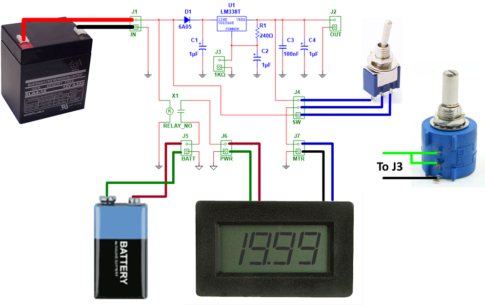
FIGURE 5.- External components connections
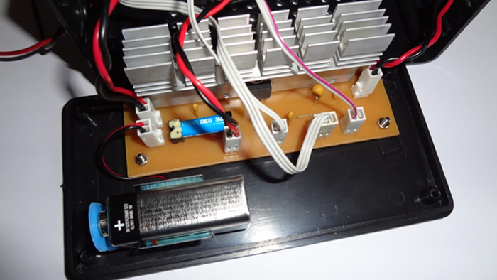
FIGURE 6.- Internal view with all components in place
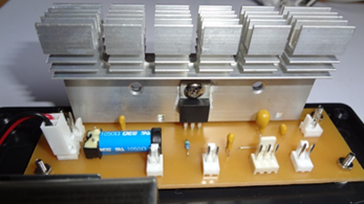
FIGURE 7.- Heatsink attached to the regulator; the reed-relay can be seen on the left (light blue body)
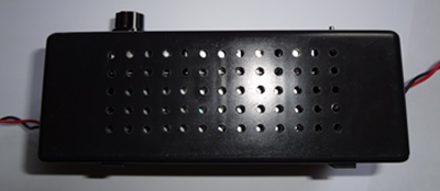
FIGURE 8.- Holes on the back of the enclosure (next to the heatsink) for proper heat dissipation
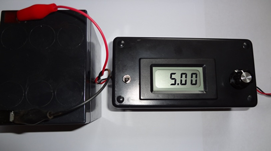
FIGURE 9.- Working power supply, connected to the SLA battery
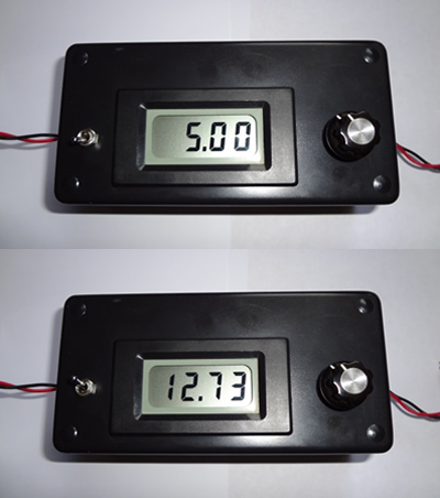
FIGURE 10.- Voltmeter showing the output (top) and input (bottom) voltage; see the positions of the switch on the left
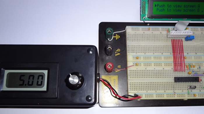
FIGURE 11.- Power supply connected to a breadboard, powering an actual circuit