Measuring the voltage (V) of a Direct Current (DC) source is usually not a problem; just measure the instantaneous value at any given moment and that would be all you need. A completely different story is when you try to do the same measurement in an Alternating Current (AC). The instantaneous value will change over time, due to the nature of this kind of signal.
What voltage would characterize the signal? The peak value? The average value? While these levels could be representative of an AC signal, there is a well defined value that usually represents it: the RMS value.
RMS (Root Mean Square) is equal to the DC value that delivers the same average power to a pure resistor as the AC signal.
There are different methods to measure the RMS of an alternating signal. In the particular case of a pure sinusoidal wave, the RMS value is equal to the peak value divided by the square root of 2:
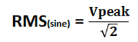
This method is used in common low-cost handheld measuring devices, by rectifying and filtering the signal (thus capturing the peak value) and applying a fix conversion factor (0.7071). Needless to say, this factor is just 1/sqrt(2). While this way to measure the RMS value is effective for pure sinusoidal signals, it fails when the signal is distorted, or simply, it is not sinusoidal at all.
Fortunately, there is a more precise way to measure the RMS value of an alternating signal, even if distorted, and this document explains how to implement it using a PIC microcontroller.
The A/D converter of a PIC will return a digital value proportional to the analog signal present at the input, with the following limitations:
- The measurement is the instantaneous value of the signal.
- Only positive values can be read.
- The full signal swing must be within the minimum and maximum reference values of the A/D.
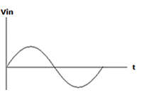
With this in mind, let’s review how to measure the true RMS value of an alternating signal. The following signal will be used as an example:
Since the PIC’s A/D can only measure positive values, a DC level must be added to the signal, so as not to lose the negative portion. At the same time, the maximum amplitude must be kept within the A/D’s reference levels, which could be done using a resistive divider. In some cases, when the signal is too small, an amplifier may be used to improve resolution. Either case, the final result should be similar to the following image:
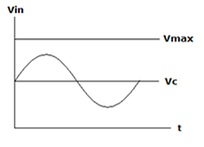
In this example, Vc represents the added DC level, and Vmax is the maximum voltage accepted by the A/D converter. Now the signal is well within the PIC’s A/D voltage window, with a good amplitude to ensure a reasonable resolution.
At this point, the capture process may begin; each capture reflects the instantaneous value of the signal at a certain time, so it is key to take several samples to guarantee accurate results. How many samples? As many as possible, and enough to capture at least one complete cycle of the AC signal.
The DC level added to the original signal must be removed from the calculations in order to have the actual RMS value. So, the following equation will be used:
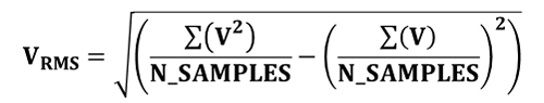
Here V is the instantaneous value of the signal, and N_SAMPLES the quantity of those values actually captured.
Practical application
For this practical example we will be using the PIC 16F1825. This particular PIC has the option to use an internal reference as the maximum value for the A/D converter, fixed at 2.048V. This value simplifies the calculations, since we just need to multiply the capture data by 0.002 to have the actual voltage (since the A/D converter has 10 bits resolution, i.e. 1024 steps, the conversion factor is 2.048V/1024steps = 0.002V/steps).
The PIC will be using a 16MHz clock and N_SAMPLES will be 1024; in this situation, considering the acquisition time and the calculations with 32-bit variables, the total time will be close to 200ms, enough to capture at least 10 cycles of a 50Hz signal, or 12 of a 60Hz one (the most typical frequencies used for domestic AC power supply).
Here is the code, programmed in CCS C, of the entire routine to measure the true RMS value of an alternating signal:
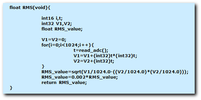 (
(Therefore, from any program running in the PIC, the RMS value can be obtained just by calling this function, for example:
Vrms=RMS();
As a final remark, make sure that the PIC is properly configured in the main program, so the capture is done correctly. In this example, the A/D converter input is on PIN_A3:
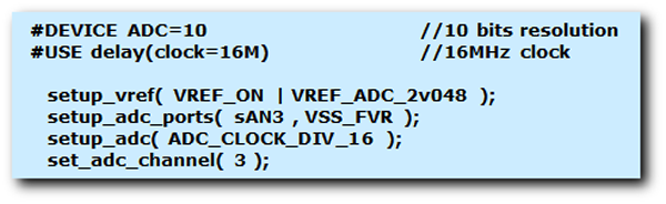 (
(Real life applications
Besides measuring the RMS voltage of alternating signals, this routine can be quite powerful when implementing power meters, for example, to measure the power consumption of a house. Using a current clamp, and knowing the standard voltage of the power line, the total power consumption could be calculated. By integrating the results in a given period of time, the energy consumption will be available, for example, in kWh, which is the standard unit to measure the energy consumed by a normal home.