Character LCDs offer a simple, yet effective way to interact with the users and convey messages, instructions and status of several variables, from the equipment to the operator. In many applications, the communication goes in only one way, and the message is just informational. However, there are many other applications in which the interaction lets the user perform some tasks, selecting options that will change the way the equipment behaves. This document will explain how to create a menu structure using a 2-line character LCD that the user can navigate, select the proper option, and then go back to the main menu after the task is finished, in such a way that it can be easily adapted to any practical design.
In modern electronic designs the use of character LCDs is quite common, due to their simplicity and low cost, consequence of their widespread usage. There are various choices, depending on the interface type (parallel, serial), the number of lines and columns (characters), etc. Fortunately, the most common types are based on the same controller, the Hitachi 44780, so the instructions set and the communications protocol is the same for all of them. In this article we will be using a 2-line, 24 columns (characters) LCD, commonly referred to as 2x24, with parallel interface and LED backlight.
Figure 1 shows the basic setup used to test the firmware routines.
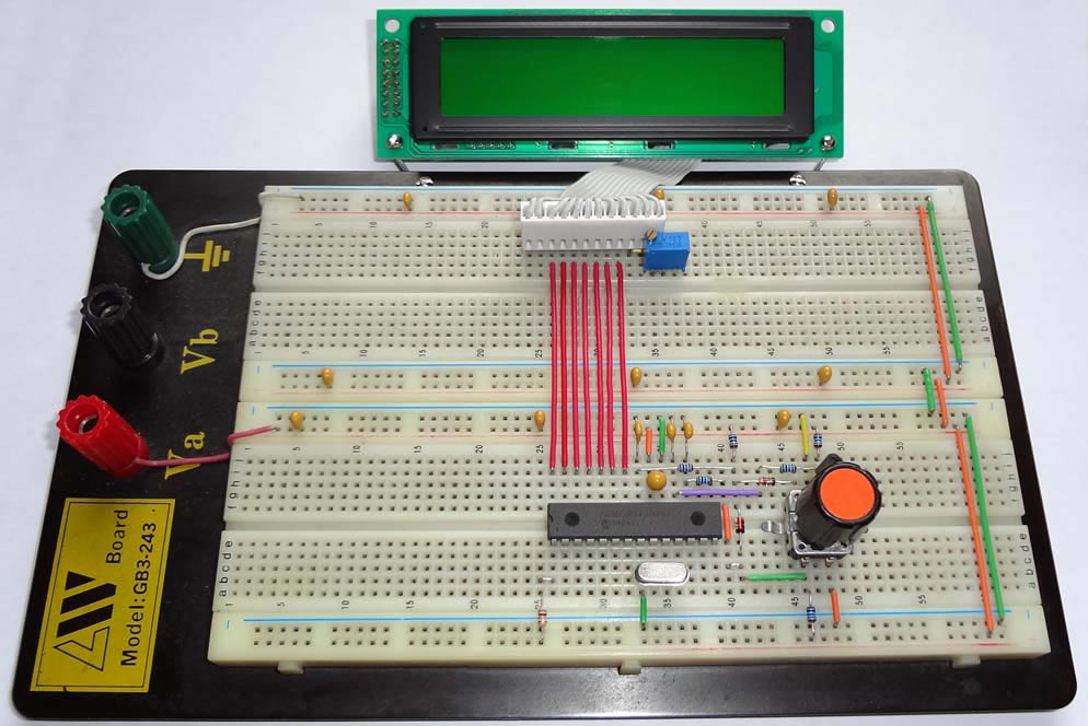
FIGURE 1.- LCD test setup, mounted on a breadboard; note the LCD contrast adjustment trimmer, T1 (blue), next to the connector
It consists of a PIC microcontroller (16F876A), a digital encoder (mechanical, 18 detents, with switch – see the “tip” on encoders for more details) and a character LCD (2x24, parallel, model 2224STLDYGBN-S, or VK2224 from Vikay). A few additional discrete components are added for proper operation. The circuit schematic is shown in Figure 2. Please note that the LCD will be working in 4-bit data mode (instead of the full 8-bit mode), to save microcontroller pins.
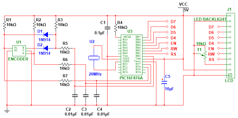
FIGURE 2.- Circuit schematic of the LCD test setup
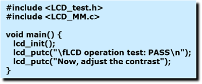
In order to test the circuit and adjust the LCD contrast (with T1), a simple program will be run, as listed below. As usual, this program is written in C, using CCS C.
 (
(The PIC16F876A configuration is also listed below. This part will remain unchanged and should be used with the rest of the programs presented in this article.
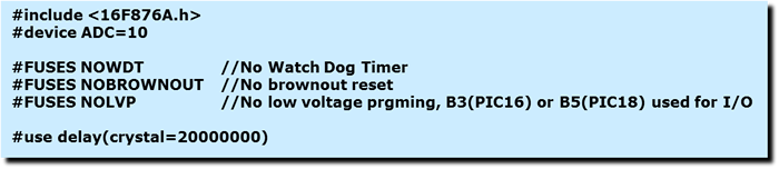 (
(The LCD driver (LCD_MM.c) is available in the Download section.
Provided the circuit has been properly connected, and the PIC has been programmed with no errors, the LCD should display 2 lines, as shown in Figure 3.
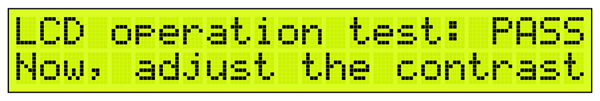 FIGURE 3.- LCD test screen
The LCD contrast should be adjusted by turning T1, either clockwise or counterclockwise, depending on how the characters can be distinguished from the background. The ideal point is when the character can be clearly seen, but the background dots cannot yet be noticed, or they are only slightly visible. This situation may change depending on the angle from which the LCD is seen, so at the end the adjustment position will depend entirely on the user's preference. The goal is to be able to clearly distinguish all characters.
Figure 4 shows the program running, with the LCD contrast properly adjusted.
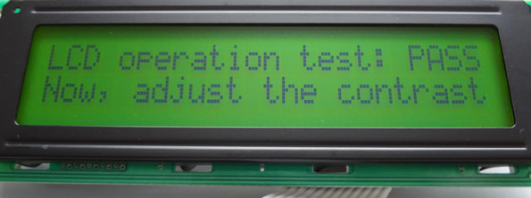 FIGURE 4.- LCD properly adjusted
Let’s review now how to create a menu that the user can navigate by rotating the encoder, and select the desired option by pressing the switch.
Menu structure
The menu we will be creating should have the structure presented in Figure 5.
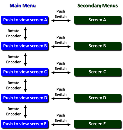 FIGURE 5.- Menu structure
There is a Main Menu (in blue), with 5 different options (A to E), moving from one to the next by rotating the encoder, clockwise (down) or counterclockwise (up). In order to select any of the options, the user must press the encoder’s switch. The Main Menu disappears, and the screen corresponding to the selected option is shown (green). The program will be doing whichever task is associated with this option, and only a new push of the switch will bring the Main Menu back. It would be possible to return automatically to the Main Menu once the routine has been completed, or after a given time, but for the sake of clarity and simplicity, all routines will return after a switch push.
Implementing the menu on the LCD
Since we are using an LCD with 2 lines, it is possible to accommodate 2 options of the Main Menu at a time on a single screen, as shown on Figure 6.
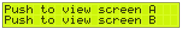 FIGURE 6.- Two menu options in a single screen
In this situation, if the user presses the switch, which one of the options will be selected? To solve this ambiguity, a new character needs to be used: the cursor (Figure 7).
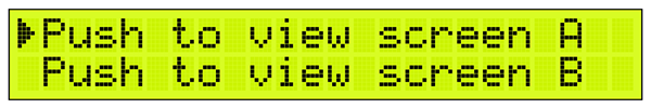 FIGURE 7.- A cursor has been added to the left
The option marked by the cursor will be the one selected when pushing the switch. When rotating the encoder, the cursor will be moved first, before changing the screen. Only when the cursor reaches the end of its movement (it can only move between line 1 and 2), a new menu option will appear on the screen, unless the last option has been reached. In this case, no further movement is possible, and the encoder should be rotated in the opposite direction. Figure 8 shows all the possibilities and the navigation logic.
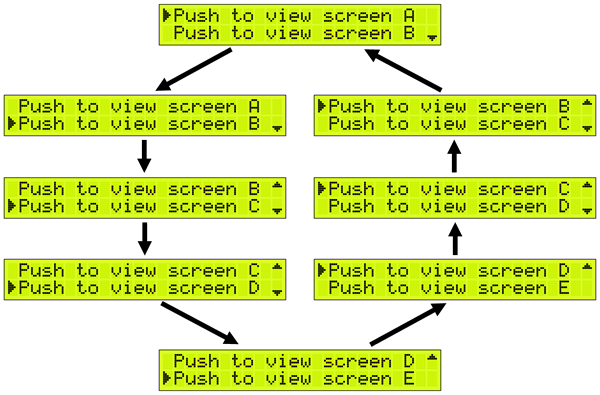 FIGURE 8.- Main Menu navigation logic
There are 2 new characters added at the end of each line: small arrows pointing up and down. These arrows are included to tell the user that there are more menu options, either up, down or in both directions.
This is the complete Main Menu navigation scheme. At any time, it is clear which option is selected, and a push of the switch will send the program to the routine indicated by such option. Figure 9 exemplifies this action, which has been already explained.
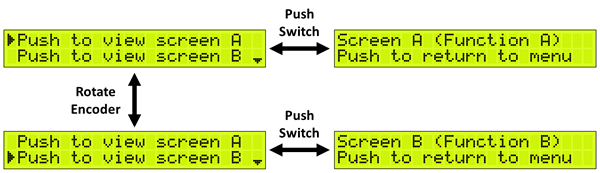 FIGURE 9.- Menu options' selection
Before moving to the actual program explanation, a quick note is required, in case you wonder which standard characters are being used to represent the cursor and the arrows. The answer is none, those 3 elements are “user defined graphics” (the LCD lets the user define up to 8 custom graphics at a time), and Figure 10 shows the actual pixel design and the binary code of each character.
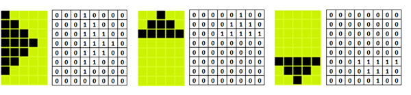 FIGURE 10.- User defined graphics
These will be created in our program, in the Function called “graphics()”.
Program
The program design is quite straightforward; the core is the Main Menu, the list of the options and the navigation algorithm. The satellite Functions are the destination of each option when selected, and the service Functions perform the “housekeeping” tasks, such as defining the user graphics or reading the encoder (this one triggered by the external interruption). In the Download section you will find all the program files, including the LCD driver, as previously indicated.
The navigation algorithm is probably the most valuable section of the program, thus it will be described here in more detail.
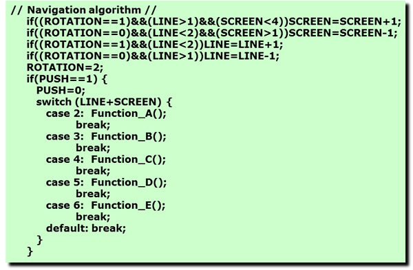
The variable LINE is the cursor position, therefore it can only be 1 or 2 (line 1 and 2 of the LCD, respectively). SCREEN represents the different menu screens, in this case 4 (not to be confused with the menu options, which are 5). So, it can only go from 1 to 4. ROTATION may contain 0 (encoder rotated counterclockwise, CCW), 1 (clockwise, CW) or 2 (no rotation), while PUSH can be 0 (no push) or 1 (encoder switch pushed).
Every time the encoder is rotated, the direction is first evaluated. IF it is CW (1), AND the cursor is in line 2 (LINE>1) AND the screen is not the last (SCREEN<4), THEN the LCD changes to the next screen. A similar logic is applied when the rotation is CCW (0), now considering that the cursor is in line 1 (LINE<2) and the screen is not the first one (SCREEN>1). If by any chance the cursor still can be moved to the next line, then the screen will not change, but LINE will be increased or reduced by 1.
If at any time the switch is pressed (PUSH==1), the program will jump to the Function indicated by the sum of LINE + SCREEN. By this method, the jump will always be to the menu option indicated by the cursor, in the corresponding LCD screen.
Startup option
Sometimes it may be desired that the unit, upon power-up, starts directly into a particular routine (Function), instead of the Main Menu. For example, if the device is a power supply, it may be desirable that it goes directly to the voltage and current control/measurement routine when the power is applied, since this is the most used function, and most of the time the user will be interacting with this screen only. Occasionally the user may want to change some other parameters, or measure additional variables, and in this case the Main Menu will be reached, by pressing the switch.
This is quite simple to achieve in our program, just by loading the navigation variables with the proper values during the program initialization. The program flow will go as before, the Main Menu will be reached, and immediately jump to the Function indicated by the initial values. For example, the following initial values will send the program directly to Function A upon startup:
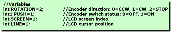
The key change here is the value of PUSH. Usually it should be 0, so the program stays in the Main Menu, showing the first LCD screen, with the cursor pointing at the first option ("Push to view screen A"). However, when loaded with 1 upon startup, the program will assume that the switch has been pressed, so it will jump to the Function indicated by LINE + SCREEN, in this case Function A. After that, the program will behave as usual, until the unit is turned off and on again, repeating the same flow.
Applications
The basic menu structure already explained may be used in various applications, when several options are presented to the user, and a direct interaction is required. The complexity of the menu is only limited by the microcontroller’s capacity in terms of memory, and it can go very deep, with several sub-menus, when using large memory devices. Here we have seen very simple Functions that only displayed a message on the screen. In real life, these Functions will be doing something useful, and in some cases they may even contain a sub-menu with several options. In any case, the basic blocks explained here are all you need to design much more complex projects.