Most electronic designs require feedback from the surrounding environment for their correct operation, either to know the status of a certain variable, e.g. the distance travelled by a robotic arm, or to receive instructions from a human operator. In modern electronics, where the core of the design resides often in a microcontroller, the use of digital encoders plays a central role in providing the external feedback. One particular type of encoder, the incremental contacting encoder, will be analyzed here, and all the hardware and software requirements will be explained in order to successfully use these devices as a reliable microcontroller interface.
There are several types of encoders, each particularly suited for a given application. Based on the data they present through the connection pins, there are absolute and incremental encoders; the first type providing the precise position of the encoder, the second one only showing variations, from one state to the next, if the shaft was moved clockwise or counterclockwise. Based on the construction, there are optical, mechanical (contacting), magnetic, etc., reflecting the way in which the displacement is captured. Based on the path of the movement, there are rotary, linear, etc.
The variety of types of encoders is quite large, and within each type there are sub-classifications, so the options are almost endless.
For the purpose of this analysis, I have selected one specific type: the Incremental Contacting Rotary Encoder. Why? Simply because it is a low cost, readily available encoder, perfectly suited for prototypes and hobby projects.
From this category of encoders I will be using one sub-class: an encoder with mechanical “detents”, and that has the same number of detents than pulses. These concepts need further explanation for those not familiar with encoders.
Understanding incremental contacting encoders
The basic schematic circuit of this kind of encoders is shown in Figure 1.
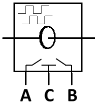 FIGURE 1.- Diagram of a basic incremental contacting encoder
It essentially consists of two switches that close and open in sequence when the encoder shaft is rotated (I will be referring to rotary encoders only, for the sake of simplicity, and since they are extremely common). In order to measure this activity as voltage level changes, e.g. 0V and 5V, the circuit in Figure 2 will be used.
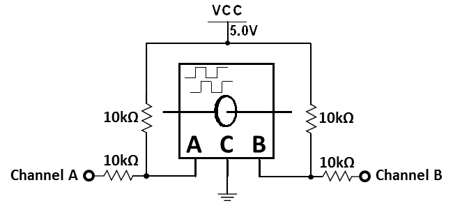 FIGURE 2.- Encoder connections
So each time the shaft is rotated, there will be a sequence of pulses coming out of each channel of the encoder; these pulses are shown in Figure 3, and it can be clearly seen that both channels have a phase shift equal to a quarter pulse, or 90°. This is also known as the two channels being in quadrature, thus the output of the encoder is referred to as “2-bit quadrature code”.
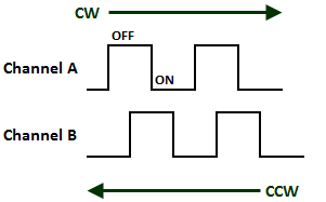 FIGURE 3.- Encoder output pulses
Figure 4 lists all possible combinations of this output, when rotating clockwise or counterclockwise. For those familiar with binary codes, you may notice that this is a 2-bit Gray Code system.
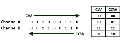 FIGURE 4.- Encoder output
One of the advantages of this system is clearly seen: only one bit changes per transition, which is fundamental in the accurate detection of the movement, particularly in contacting encoders, where the mechanical bounce of the contacts may create false readings during a bit change. This concept will be further developed later in this article.
Encoders with “detents”
The example previously seen does not consider any particular state to be the “rest position”, therefore the encoder, when no external force is applied, may be in any given position. With the use of detents, the encoder rest position is well defined, which greatly simplifies the decoding task. A detent is just a mechanical stop, where the encoder shaft positions itself when there is no external force to move it. This position is synchronized with one of the four output combinations, for example 1, 1 (both channels open, which means a high level based on the circuit used above).
So every time the shaft is moved, it will go from one detent to the next, making a complete cycle each time. Therefore, between two consecutive detents, the four output combinations can be read from the encoder, always returning to the rest position (1, 1 in our example).
Cycles and detents
Within a certain type of rotary encoder, there are various choices depending on the number of cycles and detents per complete turn (360° rotation). For example, you may find encoders with 12 cycles (sometimes referred to as pulses) per turn, 18 cycles or 24 cycles. The same applies for detents, 12 detents per turn, 18 detents or 24 detents. Caution should be exercised, however, since these two options may not be offered simultaneously: while an 18 cycles / 18 detents encoder sounds “natural”, you may find an option with 12 cycles / 24 detents, which seems to contradict the previous explanations.
As a matter of fact there is no contradiction; these kind of encoders have two different “rest states”, which alternate between consecutive detents.
For the purpose of this document we will be working only with encoders with the same number of detents as signal cycles or pulses, as previously mentioned.
Theoretical and “real life” output
Figure 5 shows the expected output from an encoder with one detent (D) per cycle; the rest state is 1, 1, both switches open (OFF).
 FIGURE 5.- Encoder output pulses showing the detents positions
In order to measure the actual behavior of such encoder, I will be using an 18 cycles / 18 detents model from Bourns (PEC11R – 4 1 15 F – S 0018). All these letters and numbers have a meaning; please consult the Bourns website for further information, if desired. For our analysis, suffice to say that besides the 18 / 18 configuration this incremental contacting rotary encoder has an added switch that can be closed by pressing the shaft. This will become handy further down in this article, but does not change at all the following analysis and conclusions.
The actual output of the selected encoder can be seen in Figure 6. The shaft is rotated clockwise manually, simulating a typical user interaction.
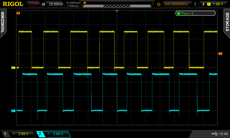
FIGURE 6.- Actual encoder's output. Upper trace (yellow) is channel A; lower (light blue), channel B
Channel A (as named in the encoder’s datasheet) is shown in the upper trace (CH1, yellow), while channel B corresponds to the lower trace (CH2, light blue). The behavior is as expected, channel A leading, and the four output combinations are present. The signal, however, does not look as “clean” as the theoretical output; there are some spikes that seem to coincide with the transitions. A closer look shows that these spikes appear in both channels at the same time, no matter which channel is changing. Figure 7 zooms in one transition… here one characteristic of contacting encoders can be clearly observed: the contact bounces during the transition.
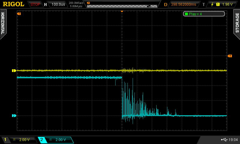
FIGURE 7.- Contact bouncing effect on channel B transition; note that channel A is slightly affected as well
I particularly selected a very noisy transition for the sake of this example, but this really happens and may make your design unusable. Furthermore, the noise is also seen in the other channel (yellow trace).
How to avoid this contact bouncing? The mechanical bounce cannot be eliminated, but the electrical effect can be avoided by using “de-bouncing circuits”. The simplest form of a de-bouncer circuit is an RC filter, as shown in Figure 8; as a matter of fact, this is the recommended configuration according to the datasheet.
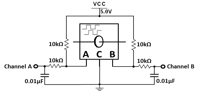 FIGURE 8.- RC filter added
Adding the capacitors to form the RC filter is enough to clean the signal, as can be seen in Figure 9.
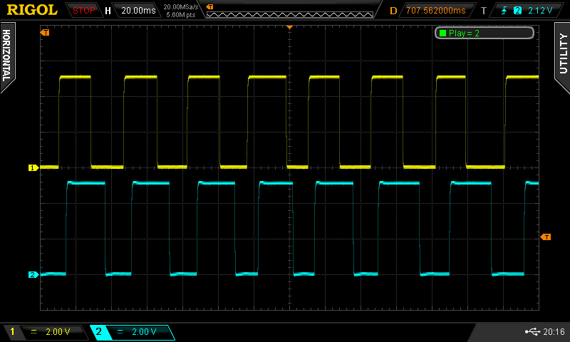
FIGURE 9.- The signal looks clean on both channels after the filter is in place
Figure 10 zooms in a transition, which is completely free from spikes.

FIGURE 10.- The transition is now completely clean from spikes, although markedly slower
There is one drawback, though: the speed of the transitions has been reduced, so the encoder cannot be used to detect high speed rotations. This is not a problem in our case, basically due to two factors: the mechanical encoder has a natural speed limit, as listed in the datasheet (60 RPM), and we will be using this encoder mainly as a human interface (which is not so fast by design). As a matter of fact, larger capacitors may be used, which improves reliability (less chance of incorrect detection) in noisy environments; values as high as 0.22µF have been tested to perform even better than the recommended values. For high speed rotation, a mechanical encoder is not the best option, and an optical one may be recommended (more precise, with clean transitions, but at the same time more expensive).
After this simple signal conditioning, the encoder is ready to be connected to the microcontroller, where a software routine will take care of the next part of the process.
Connecting the encoder to a microcontroller
Using the same electrical schematics described before, the encoder outputs are ready to be connected to any input of a microcontroller that accept a 0-5 voltage swing. Other tensions are easily accommodated by properly selecting the encoder’s power source. Can any input be used? Yes, if the software keeps reading them periodically (polling) to detect any transition. There is, however, a more elegant and practical way: use the external interrupt input to trigger an event when a transition is sensed. All microcontrollers must have at least one external interrupt, and the PIC 16F628A is not an exception. We will be using this common PIC for this example, but it works with others as well.
So the concept is quite simple: one of the encoder’s channels is connected to the interrupt pin, while the other goes to any other pin. As soon as the interrupt pin detects a transition, the interrupt service routine is called, and it will immediately check for the status of the other pin. Just by doing this, the program knows immediately the direction in which the shaft has been moved. Let’s illustrate this by using the image of the pulses with the detent position, now named as Figure 11.
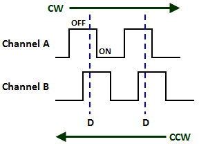 FIGURE 11.- Output pulses
Imagine that channel A is connected to the interrupt pin (which in the PIC 16F628A is PIN_B0), and channel B to PIN_B1. As soon as the encoder leaves the rest state (position D) the interrupt will be triggered by the falling edge of channel A (the interrupt is set to be triggered only by a HIGH-LOW transition). There are only two choices here: moving clockwise (CW), it will find channel B in a high level (5V); moving counterclockwise (CCW), channel B will be low (0V) when channel A falls. So, by reading PIN_B1 (where channel B is connected) as soon as the interrupt service routine is called by the transition of channel A, the direction of the rotation is known: HIGH means clockwise, LOW means counterclockwise.
Here the advantage of the Gray Code previously mentioned is obvious; when channel A changes, channel B is already in a very stable state, far from any transition, since only one bit (channel) changes per transition. This further eliminates any remaining effect of contact bouncing, assisting the hardware filter to accomplish this task.
After reading the PIN_B1 status the interrupt routine returns to the main program and it is ready to be triggered again on the next falling edge of channel A, repeating the same steps. The direction is saved in a Boolean variable (0 or 1), so it can be used by any other routine, e.g. increasing the volume of a radio receiver.
Real life behavior
If the previous instructions are followed carefully, and the same model of encoder is used, the actual behavior will not be as perfect as described. There will probably be jumps in the sequence, detecting the wrong direction, activating the interrupt more than once between two detents, etc. The first instinct will be increasing the filter’s time constant, with a larger capacitor, but the problem will remain.
Only a detailed examination of the encoder’s channels behavior will show the reason of these strange occurrences; Figure 12 shows both channels again, now moving the encoder at a much slower speed, giving the contacts time to settle in the detent’s position (rest state).
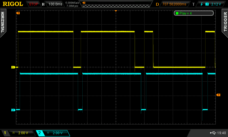
FIGURE 12.- Behavior at slow rotation speed; channel A activates during the third rest position (goes LOW), which is unexpected
The rest state must have both channels in the OFF state, meaning high level (5V). While this is always true for channel B, channel A, on the other hand, sometimes tends to rest in the ON state (0V). This should not be normal, and one may think of a defective part. However, after testing several encoders of the same brand and type, the same behavior repeated over and over again. Without further evidence to prove any theory, I can only speculate that there must be some mechanical difficulty to synchronize both channels with the detent, so only one gets perfectly aligned. In all the cases I tested, channel B seemed to be the reliable one. Does it mean that the method previously explained does not work? Not at all, it works perfectly well. Just use channel B to trigger the interruption (PIN_B0), and then read A (connected to PIN_B1 now). This is possible because A is always in the right state when B transitions, it is only later that it may change to a different unexpected state. Using B as the trigger, the logic is reversed: if A (PIN_B1) is HIGH, the direction is counterclockwise; when A is LOW, then the movement is clockwise.
You may wonder, how do I detect which channel is the good one, without a digital storage oscilloscope? It is very simple: just grab a continuity tester (or any low current instrument that sounds when the terminals are shorted) and touch the center pin and one of the channels. Rotate the encoder slowly, from detent to detent, until a full rotation is completed. The good channel will only emit a short sound between detents, but will remain open in the rest positions; the other, will behave well in most rest positions, but eventually in a few of them will remain closed. So, avoid this channel as the source of your interruption.
Using the switch
When describing the model of the encoder I would be using, I briefly mentioned that it also has a switch that closes by pressing the shaft. This switch is very useful in certain applications, for example when navigating menus. While the encoder rotation navigates through the various menu options, pressing the switch actually selects the desired choice. And all this interaction can be done using a single encoder, saving space, complexity and, above all, money.
We previously considered a couple of ways to read the encoder: by polling or by interruption. Reading the switch is no different; both methods are valid, although the interruption is preferred. Do we need two external interrupt pins to read both the rotation and the switch? Fortunately no, with a few additional components the same interrupt can be accurately triggered by both events, provided they do not happen simultaneously (rotating and pushing at the same time, which must be avoided, and is not a natural movement anyway).
Figure 13 shows the schematic circuit used to add the changes done by the rotation and the switch closing, avoiding interference between them. Basically it is a logic “AND” gate.
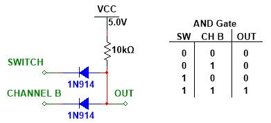 FIGURE 13.- Discrete AND gate to connect the switch and channel B
While any of the changes may trigger the interrupt, it is key that they remain isolated at the encoder’s side, in order to be able to detect which one triggered it. Therefore, the rotation does not affect the switch output and vice versa. The use of a logic gate makes this behavior possible.
In Figure 14 the full circuit schematic is presented, including the connections to the microcontroller; note the double connection of the switch pin (S1), through the gate to the external interrupt pin (PIN_B0), and also directly (via a 10kΩ resistor) to PIN_B2. The LEDs connected to the microcontroller are there just for demonstration purposes, as a visual indicator of the encoder’s performance.
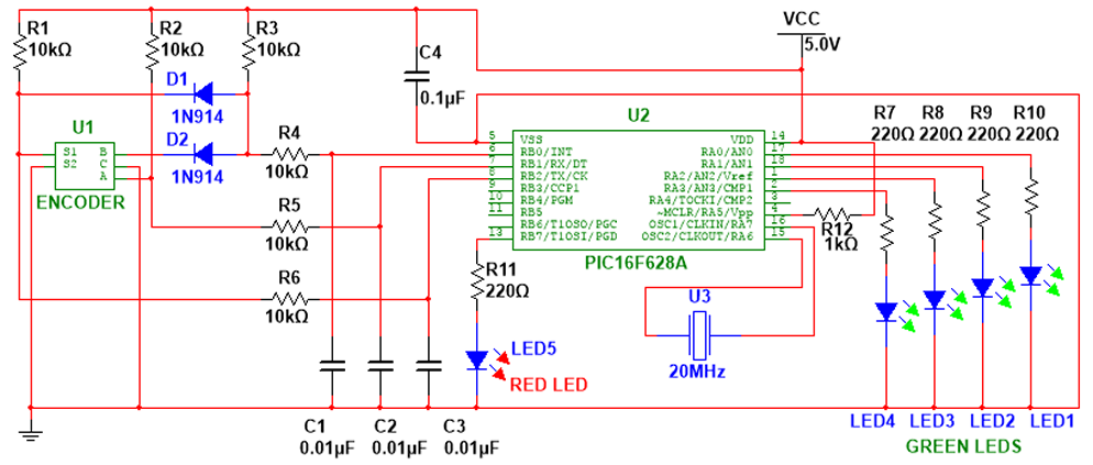
FIGURE 14.- Full circuit schematic; C1, C2 and C3 may be replaced by larger values (e.g. 0.22µF) for improved performance
The test circuit mounted on a breadboard is shown in Figure 15.
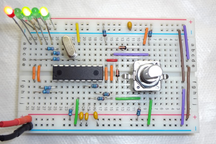 FIGURE 15.- Test circuit on breadboard
The least significant bit (LSB) is on the right, so the counter (green LEDs) shows 5 (binary 0101), and the red LED is ON, indicating that the switch was pressed at least once. All these concepts will be much clearer when the software is explained.
Software routines
With the hardware fully explained and connected to the microcontroller, the last section of this tutorial will describe the required software routines to properly decode the information. The concept, without using the switch, was briefly explained before, and it is quite simple: when the interrupt pin detects a falling edge, the interrupt service routine is called, the status of the other pin of the encoder is read, and according to it the direction is known, CW or CCW.
The use of the switch requires another question to be answered before deciding the direction: who triggered the interruption?.
In order to answer this question, the first thing that the routine must do is check the status of the switch pin, connected to PIN_B2. If it is LOW, then it was the switch that was pushed; otherwise, if HIGH, the trigger was the encoder’s rotation. Depending on the outcome of this evaluation, two different actions are performed:
- The switch pin is LOW, so the switch was pressed: set the PUSH variable (Boolean), and load a 2 in the ROTATION variable.
- The switch pin is HIGH, the switch was not pressed: clear the PUSH variable, and load 0 or 1 in ROTATION, depending on the status of PIN_B1.
You may notice a fundamental difference with the logic described before in this article; the variable storing the direction of the rotation is no longer Boolean, since a third state is added: absence of rotation. This is required since, when the interrupt is triggered by the switch, the main program will interpret that a rotation occurred if the ROTATION variable is 0 or 1.
Therefore, here is the list of possible values for both variables and their meaning:
ROTATION:
- 0 = rotating counterclockwise (CCW)
- 1 = rotating clockwise (CW)
- 2 = no rotation
PUSH:
- 0 = switch open
- 1 = switch closed (pushed)
The full program is listed below. After the variable and functions definitions, the main program configures the interruptions and enters an endless loop, that checks the status of the variables ROTATION and PUSH to decide what to do next. ROTATION increases or decreases a binary counter (0 to 15) that activates the four LEDs according to the count, while PUSH lights a fifth LED ON and OFF alternatively when pressed. The interrupt service routine (EXT_isr), when called, runs the previously described encoder status evaluation, updating the variables accordingly.
Program
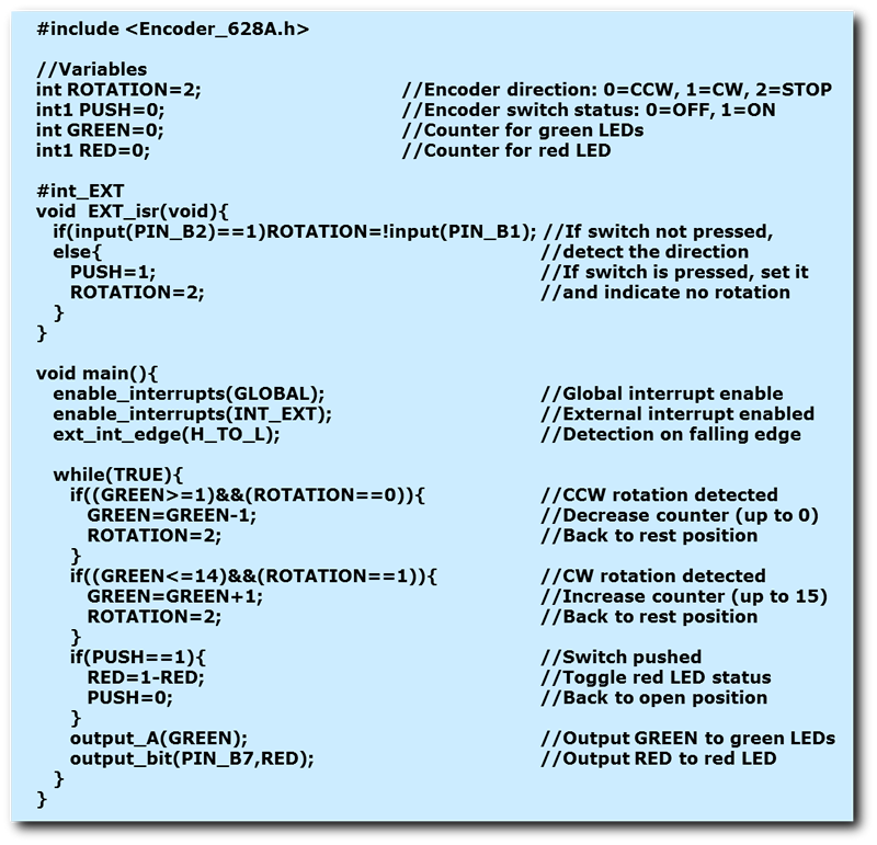 (
(Only four variables are used in the program: the two well known, ROTATION and PUSH, that contain the status of the encoder, and two new, GREEN and RED, containing the status of the external LEDs (the names are indicatives of the colors they control). While ROTATION and GREEN are 8-bit wide (int), PUSH and RED are Boolean (int1).
The interrupt routine is quite simple, as previously indicated: when called, if the status of PIN_B2 is high (switch open) then the status of PIN_B1 (channel A) is loaded into ROTATION. As a matter of fact, the opposite of PIN_B1 is loaded (the simbol "!" indicates that), to maintain the convention that 0 means CCW, and 1 means CW. If, on the other hand, PIN_B2 is low, then the switch has been pushed, so PUSH will be 1 and ROTATION will contain 2 (encoder stopped).
The main program enables the interruptions at various levels, and indicates that only the falling edge will be detected; after that, an endless loop monitors the status of both variables, ROTATION and PUSH, to see if there has been any change. In case of ROTATION, since it will be increasing or decreasing a counter (GREEN), the value of the counter is also evaluated. We are using only four green LEDs, so the binary count can go from "0000" to "1111", or 0 to 15 (decimal). To keep the counter within these limits, the count can decrease only if the value is greater or equal to 1, and on the other extreme, it can increase only if it is lower or equal to 14. As soon as the counter is updated with the new value, ROTATION is set to 2, so it will not change the counter again unless the encoder is actually moved.
In case of PUSH the evaluation is quite straightforward: if 1, then toggle the status of RED, and reset PUSH (0).
Finally, the actual LEDs are turned ON (1) or OFF (0) according to the values stored in the corresponding variables. While the red LED will just show if the switch has been pressed, the four green LEDs form a binary counter, which changes with the rotation of the encoder.
As with any program written in C for the PIC family, the proper configuration file must be included for the program to compile and run (Encoder_628A.h). The file is listed below.
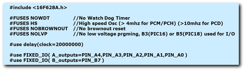 (
(A final note: the program has been written in CCS C, but it can be easily ported to any other compiler.
This concludes this tutorial; the encoder-reading routine can and will be used in more complex projects. Feel free to explore the possibilities.