Quite often there is a need to display the results of a given process that occurs inside a microcontroller, either alphanumerically, graphically or by a combination of both methods. Several alternatives are available nowadays, ranging from simple to complex, cheap to expensive, depending on the level of detail required and the capabilities of the used hardware.
Here I will present a simple yet very powerful display interface, using a standard TV set - with the only requirement that it has an available video input - that will let the user show characters - the full extended ASCII table plus 32 User Defined Graphics - and all sort of drawings in a 320 by 192 pixels screen matrix.
Additionally, the circuit uses a standard serial port for communicating with the external microcontroller, at 4 different speeds, making it suitable for interfacing with most of the current chips and platforms, e.g. PIC Microcontrollers, Arduino, Raspberry Pi, etc., requiring just 1 available pin for the default connection.
There are many ways to show the results of a microcontroller process in a visual manner, ranging from very simple and cheap, such as lighting an LED, to much more complex, and expensive, for example, using a high definition video display to present data, charts and graphics. With the added complexity, there is an increasing degree of difficulty for the user to control the interface, requiring more programming skills and frequently demanding a very scarce resource: available microcontroller pins.
A quite common method nowadays, with a very good balance of display capabilities and ease of use, consists in using character and graphic LCDs to show information. There are plenty of libraries available and software drivers that simplify the interface, and in the case of devices using serial connection, only a few microcontroller pins are needed. While this seems a perfect balance, they usually lack one particular aspect: large screen size. The larger the display, the more expensive it becomes, so this usually impose a limitation on how big you go.
What if there was a method to use a large display to present information, in the form of characters, charts and graphics, even animated, at a very low cost and using as few as just one microcontroller pin? Here is a hint: you will be using a large display device already available at your home (at least in a large percentage of cases), and there is a certain probability that one of such devices is not being currently used.
Yes, you are guessing right, such display device is a TV set, and particularly an “old” CRT-based unit. With the evolution of TV formats and technologies, over-the-air transmission becoming digital, screen aspect ratio evolving from the traditional 4:3 format to the widescreen 16:9, resolution increasing from 480i to 720p, then to 1080p, and now 4k, the old devices cannot keep-up with the picture quality demand. With a digital converter, it is possible to keep using the old TVs to see 4:3, 480i resolution content, but with the marked price decrease of new LCD-based, high-definition, digital televisions, it is certainly probable that the old CRT unit has been moved from the family-room to the storage place.
OK, so you have the TV, now how can a microcontroller show images in a TV screen? The “magic” is performed by a circuit interface called “TV Character Generator”.
Circuit design
The TV Character Generator has been designed with these principles in mind:
- Works with any NTSC (59.94Hz) or PAL (50Hz) TV, CRT or LCD-based, 4:3 or 16:9, with the only requirement that it has a video input available (yellow RCA connector).
- Has a standard interface with any microcontroller, using very few pins, preferably just one.
- Easy to control, with C language drivers available.
- Versatile, letting the user display standard ASCII characters, extended characters, user-defined characters, plus allowing access to each individual pixel so any kind of graphics, dots and lines can be displayed, in a grid of 40 by 24 characters (8 x 8 pixels each) or 320 by 192 pixels. Besides, a choice of black or white background is available, for added flexibility.
- Full control of the active screen position by software, lets the user displace the area both vertically and horizontally, useful for analog TVs, which may not be all adjusted the same. Besides, two brightness levels adapt the display to the environment lighting conditions.
- Very affordable and constructed with standard components.
The circuit schematic is shown in Figure 1. As can be seen, the design is quite simple, just a few components to perform the digital and analog functions to convert a stream of microcontroller commands into a video signal, with all the features required by the TV standard (for more on TV signals and standards, see the Project “Video Pattern Generator”).
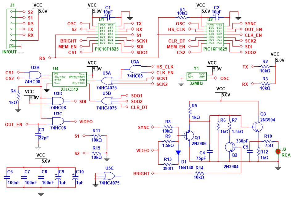
FIGURE 1.- Full circuit schematic
The true power of this design resides in the software programmed into both PIC microcontrollers, U1 and U2. These chips have dedicated functions: U1 acts as the user interface, receiving commands from an external microcontroller through the serial port, interpreting such commands and generating the proper bytes to be stored in the SRAM (U4), at particular locations so they form a coherent image when displayed on the TV screen. U2 has the responsibility to generate the TV synchronisms, and read the memory at the correct moment, so the picture frame appears stable and always in the same place. The logic gates (U3 and U5) act as traffic controllers, so the digital signals can reach the intended destinations avoiding collisions between them. Finally, the analog circuit, formed by 3 transistors and discrete passive components, combines synchronism, video and brightness information, and outputs a non-interlaced, NTSC-M or PAL-B,G,H,I,N compatible video signal, to be fed into the 75 Ω input of the TV set, usually identified as a yellow RCA-type female connector.
Screen layout
The generator will create a virtual grid on the TV screen, composed by 320 pixels wide by 192 pixels tall. These pixels can be in one of two states, either on or off, and in this way the image is created. The user has the freedom to access and activate/deactivate each one of the 61,440 pixels, to create any pattern. Figure 2 shows a diagram of this virtual grid.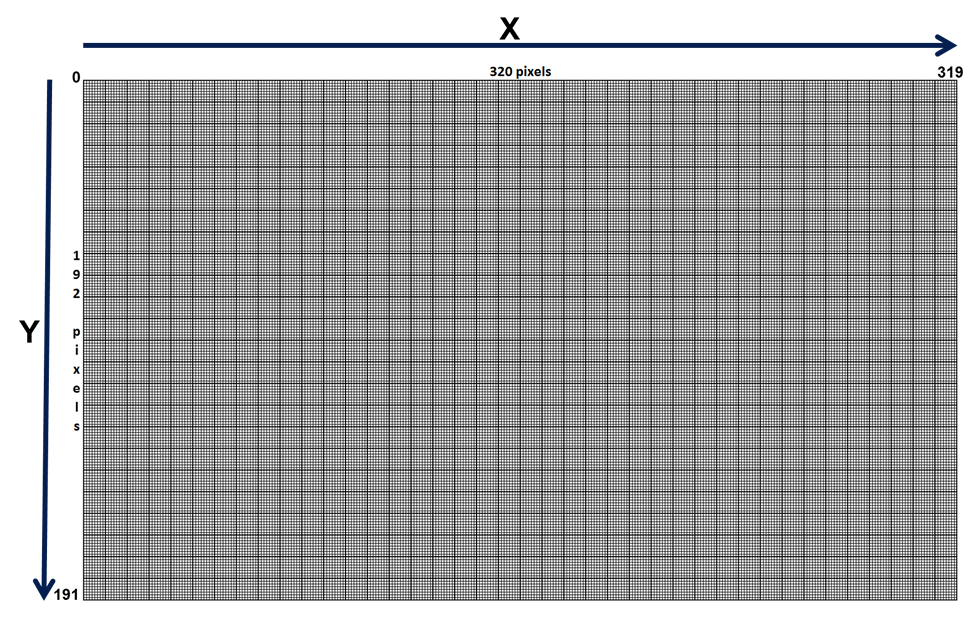
FIGURE 2.- Screen graphic grid, 320 x 192 pixels
In order to address each individual pixel, an X-Y coordinate system has been introduced, with the origin in the upper left corner. Both coordinates start at 0, therefore the maximum value of X is 319 (at the right border), while Y may go up to 191 (bottom border). Please note that the maximum X value exceeds 1 byte capacity (255), which will have practical implications that will be discussed later.
This grid, while useful for displaying graphics (therefore it might be called “graphics mode”), it is unpractical to show characters on screen, in the form of letters, numbers and symbols. It would be a waste of time and microprocessor resources if the user had to draw each letter, pixel by pixel, every time a text is written. For this reason, a lower resolution grid has been created within the high resolution structure. This is represented in Figure 3, and it is what we will call the “character grid” (or “text mode”, as opposite to the previous one). This grid has 40 characters wide by 24 characters tall. The 960 positions can be addressed individually by an X-Y coordinate system, like the graphics mode, starting at the upper left corner, with the difference that X will go up to 39 and Y up to 23.
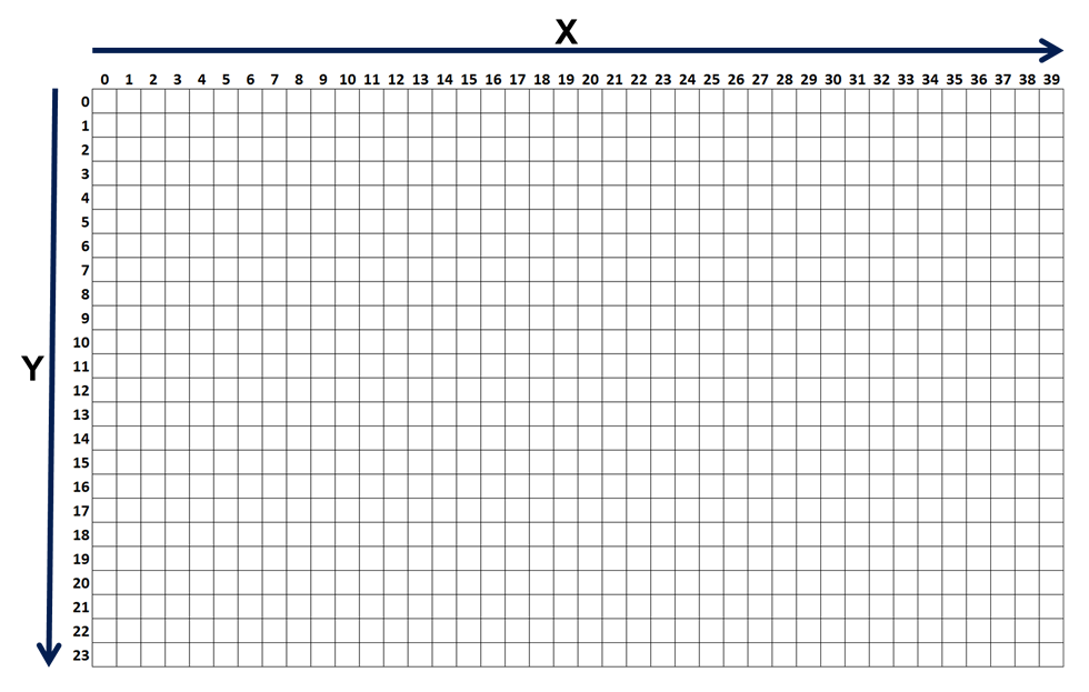
FIGURE 3.- Character grid, 40 x 24 characters
With a simple math calculation it can be easily seen that each “character” is in fact a matrix composed by 8 pixels wide by 8 pixels tall, as show in Figure 4. All ASCII symbols, from code 32 to code 255 (decimal) have been already designed and stored in the program memory, so the user just needs to call the code and the character will be automatically drawn in the place indicated by X and Y coordinates.
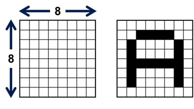 FIGURE 4.- Empty 8 x 8 matrix and representation of the character "A"
For added flexibility, the first 32 codes (0 to 31) have been left available for the user to design any character, picture or symbol; these are called User Defined Graphics, or simply UDG. See Figure 5 for an example on how an UDG is designed and each byte is coded. Bear in mind that UDGs are stored in RAM, so they are deleted when the power is removed.
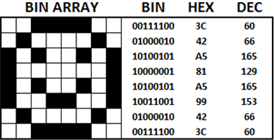 FIGURE 5.- UDG with its 8 bytes coded in Binary, Hexadecimal and Decimal
Since each pixel can only be activated or deactivated, it is clear that only black and white images can be shown. There are several reasons behind the decision not to include color, among them are the simplicity (thus lower cost) of a black and white design, added to the higher resolution achieved in an analog CRT; colored lines at this resolution may appear blurred and hardly visible. Just as a technical reference, the video input of a TV set is designed to accept signals up to 4.2 MHz, and we are working at a maximum of 4.0 MHz, pushing the analog TV capabilities to the limit.
Despite being black and white, the design is flexible enough to accommodate some variations. For example, the background can be either black or white; therefore, the characters can also be white over a black background and black over a white background. Figure 6 shows these various combinations, which undoubtedly will enhance any text presentation.
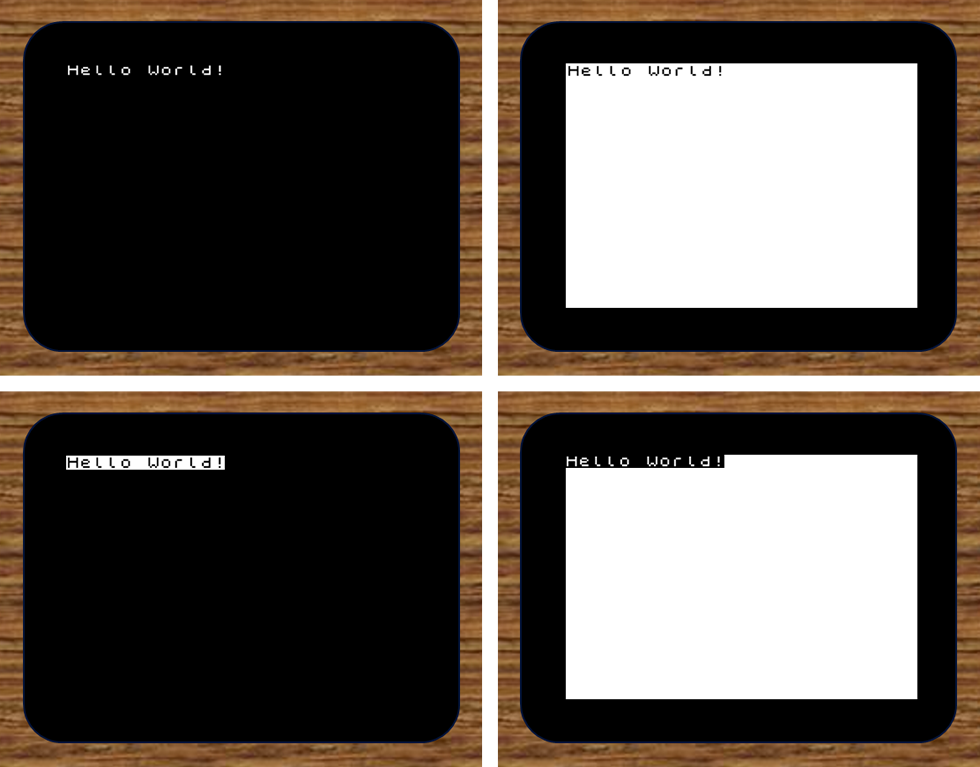
FIGURE 6.- Different display styles, by changing the background and character presentation
Please note, as it is evident in the diagrams, that when using a white background there will always be a black border around. This is by design, since the white background is in fact the full screen with all pixels activated. Obviously, in order to create an image here, the user will have to deactivate the corresponding image pixels.
Besides displaying pixels and characters, the user has access to other very useful features, all controlled by software commands.
Brightness
The user can choose between two brightness levels, high and low, to accommodate for different environment lighting conditions (Figure 7).
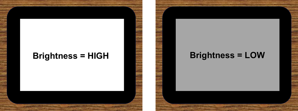
FIGURE 7.- High and Low brightness levels
Vertical position
The full working area can be moved vertically a total of 21 lines, from 0 to 20, to accommodate for different vertical adjustments that may be found in analog TVs, so the user can always have the display area in the center position. Default value is 10 lines, suitable for most TV sets.
Horizontal position
Similar to the vertical adjustment, the same can be done with the horizontal position. In this case there are 5 discrete settings, from 0 to 4. Here the displacement is measured in time units, in this case microseconds (µs). Default value is 2 µs. Figure 8 shows the different position adjustments.
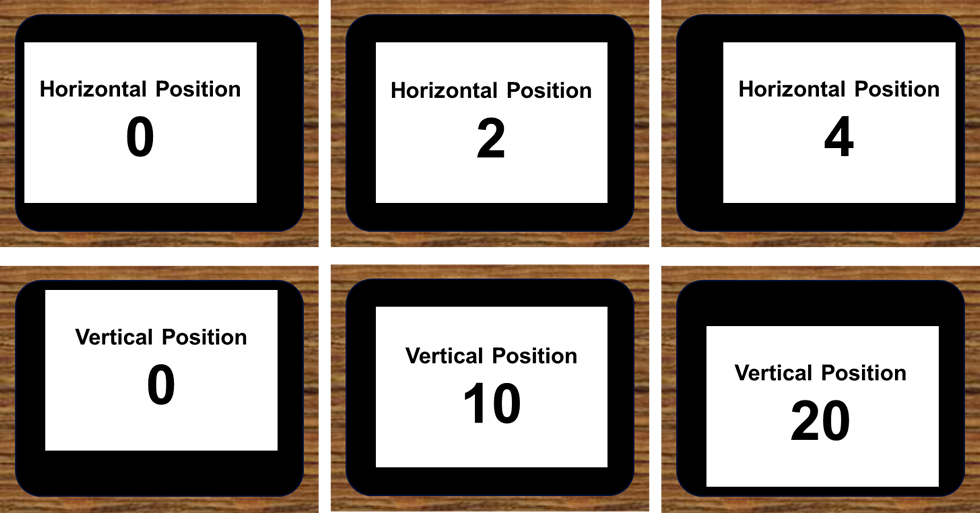
FIGURE 8.- Horizontal and Vertical screen position adjustments
Software commands
All functions of the generator are controlled by software commands, with the only exception of the serial port speed selection, which is done by 2 hardware connections. Each software command is 1 byte long, and it is always the first byte to be sent in any instruction sequence. These sequences can be just 1 byte long (just the command byte sent, e.g. when setting the brightness level or the screen position) up to 9 bytes long (the command byte plus 8 other bytes, e.g. when creating an UDG). The full list of commands, with the sequence length in bytes, is shown in Figure 9.
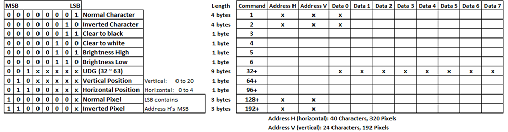
FIGURE 9.- Full commands list including the bytes sequence for each
Displaying characters
Commands 1 and 2 are used to display characters on screen, in the so called "text mode". Both function exactly the same, with the only difference that command 1 will display white characters over a black background (“Normal Character”), while command 2 will do the opposite combination (“Inverted Character”). The full sequence includes a total of 4 bytes that must be sent in the following order:
- Byte 1: Command – 1 or 2
- Byte 2: X coordinate (horizontal position of the character on the grid) – 0 to 39
- Byte 3: Y coordinate (vertical position of the character on the grid) – 0 to 23
- Byte 4: Character (ASCII code of the character or UDG) – 0 to 255
Clearing the screen
The screen may be erased in two ways: leaving it completely black or completely white (with a black border as explained before). This is a very simple sequence, just the command byte is required: command 3 will clear the screen to black, command 4 will clear it to white.
Screen brightness
Another very simple sequence is used to change the brightness of the screen, with only the command byte needed. Command 5 will set the brightness HIGH, while command 6 will set it LOW.
Screen position
Vertical and horizontal position of the grid can be modified as previously explained, and just the command byte is needed; the difference with the previous instructions is that the command byte will contain the data as well, i.e. the vertical or horizontal displacement will be included in the command byte. Therefore, there will be as many command bytes as positions are possible, either vertically or horizontally. See Figure 10 for a bit-wise description of these commands.
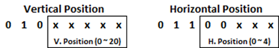
FIGURE 10.- Screen position commands bit structure
There is a base command for each direction. Vertical is 64 (binary 01000000), and the last 5 bits will contain the displacement (0 to 20). For this reason, the commands table shows “64+”, representing this fact. If, for example, the user wants to displace the screen down 10 lines, the command will be 74 (binary 01001010). In case of horizontal, the base is 96 (binary 01100000), and only the last 3 bits will be needed to indicate the displacement (0 to 4). Therefore, the commands table shows “96+” for horizontal position. To displace the screen 2 µs to the right, the command 98 (binary 01100010) should be used.
Displaying pixels
In order to set or erase a pixel in the "graphic mode", 2 commands may be used. There are a few considerations here. First of all, setting a pixel is just putting a white pixel on screen; erasing it, means putting a black pixel in the same XY coordinates. Therefore, the concepts “setting” and “erasing” work in a certain way when using a black background and in the opposite way when the background is white. In the commands list the pixel commands are called “Normal Pixel” (white) and “Inverted Pixel” (black).
An additional consideration is that each command will contain part of the pixel coordinates in the LSB (Least Significant Bit). As previously mentioned, when explaining the coordinate system of the high definition grid, the horizontal position, X, can go from 0 to 319. A single byte can only accommodate 256 values, so it would be required to use 2 bytes in order to represent the X position. To avoid this, X will “borrow” the LSB of the command byte, which is much more efficient in terms of byte-count. Therefore, X may be considered a “9-bit” byte, if such a term exists. Figure 11 shows this in a more graphical representation.
![]()
FIGURE 11.- "Bit sharing" strategy to accommodate X coordinate values that exceed 1 byte's capacity
This “bit sharing” strategy is represented in the commands table by using the “128+” and “192+” denominations for the pixel commands, which could be either 128 or 129 and 192 or 193, depending on the contents of X.
Finally, the full pixel sequence is just 3 bytes long, as listed below:
- Byte 1: Command – 128/129 or 192/193
- Byte 2: X coordinate (horizontal position of the pixel on the grid) – 0 to 319
- Byte 3: Y coordinate (vertical position of the pixel on the grid) – 0 to 191
Creating User Defined Graphics (UDG)
The first 32 codes of the character map are reserved to store the UDG. These are 8 x 8 pixel arrays, exactly like the rest of the ASCII characters, but they are stored in RAM, so the user has the freedom to change them at will. For the same reason, they are lost every time the power is removed, therefore each one of these 32 codes locations must be loaded with the corresponding graphic before the code is called to be displayed on screen. This loading process needs to be done just once, and is only required for those codes that will be actually used. To exemplify the GDU creation process, let’s use the graphic previously shown, now renamed as Figure 12.
FIGURE 12.- UDG with its 8 bytes coded in Binary, Hexadecimal and Decimal
This “happy face” is coded as 8 bytes, as shown on the right side. These are the bytes that will be stored under the UDG code, and all of them will be retrieved and displayed on the screen when the code is called.
The command to store an UDG in RAM is listed as “32+”. This denomination is already familiar, and it means that there is a base command, 32 (binary 00100000), and the last 5 bits contain the UDG code, as shown in Figure 13.
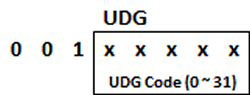 FIGURE 13.- UDG command, including the Code in the last 5 bits
The complete sequence will contain 9 bytes, the command plus the 8 bytes that correspond to the UDG design, from top to bottom. Therefore, if the user would like to store the “happy face” under the code 15, the sequence would be: 47, 60, 66, 165, 129, 165, 153, 66, 60. Needless to say, 47 is command 32 plus code 15.
In order to show this on the screen, it will be called like any other character: Command (1 or 2), X coordinate, Y coordinate, Code 15. The "happy face" will appear in the position XY.
Electrical connections
The TV Character Generator has 2 physical connectors: a 7-pin header, for the power and the communication with the external microcontroller, and an RCA-type connector, for the video output to the TV set. The function of each of the 7 pins in the header is shown in Figure 14.
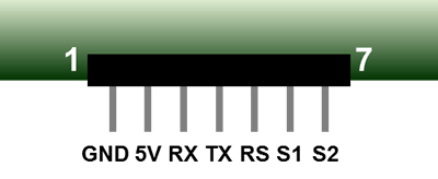 FIGURE 14.- 7-pin header, showing the function of each pin
Pins 1 and 2 are connected to the power supply (GND and 5V, respectively), while pin 3 is the serial input connection (RX). These are the basic minimum connections required for the circuit to work, as will be discussed later. Pin 4 (TX) is not currently used, but has been left available in case future versions use bi-directional communication. Pin 5 is used to RESET the unit (RS), and pins 6 and 7 select the serial communication speed (S1 and S2), as shown in Figure 15.
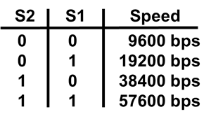 FIGURE 15.- Communication speed selection
The RESET pin is active low, and is internally connected to 5V by a 10kΩ resistor, so it can be left open if there is no need to reset the circuit. S1 and S2 are internally connected to GND by 10kΩ resistors, so the unit will work stable at 9600 bps if these pins are left open. Therefore, only the first 3 pins are required for a basic connection, as can be seen in Figure 16.
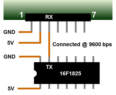 FIGURE 16.- Basic connection example, with a PIC Microcontroller
Figure 17 shows how the complete setup should be connected, including the TV set, to start working with this unit. If a faster serial communication is required, selecting the appropriate combination of S1 and S2 will change the speed. This can be done at any time, just make sure that there is no data transmission while the change is executed.
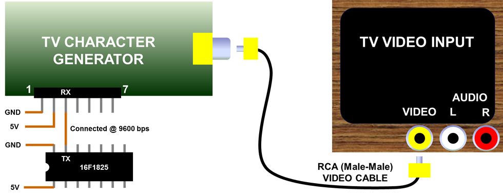
FIGURE 17.- Basic setup, at 9600 bps
Communications protocol
The communication with the external microcontroller is performed using the serial port, with the generator configured as receiver. The serial communication is set as follows:
- Parity: N
- Bits: 8
A simple line of code will configure a PIC microcontroller in C language:
![]()
In this example, the link is supposed to be established at 38400 bps, therefore in the generator side S2 should be connected to 5V (S1 left open or connected to GND) for the transmission to be successful.
Regarding the maximum speed listed, 57600 bps, this should be avoided when sending several characters to be displayed on screen, without any delay between them. In order to draw just 1 character on screen, 8 video memory locations (bytes) must be accessed and loaded, without interfering with the normal TV scan. This process takes time, and it is possible that the input buffer gets full at some point. The effect is that some characters may not be displayed as expected. Such a problem will not happen at any other of the available speeds, or if a minimum delay is set between groups of characters. Displaying pixels, as well as sending any other command, works flawlessly at any of the 4 speeds.
The generator requires around 20 milliseconds to perform the initialization tasks upon power-up or reset, so please make sure that the external device waits at least this amount of time before attempting any communication; after this initial waiting period, all communications may proceed without delay.
Basic test
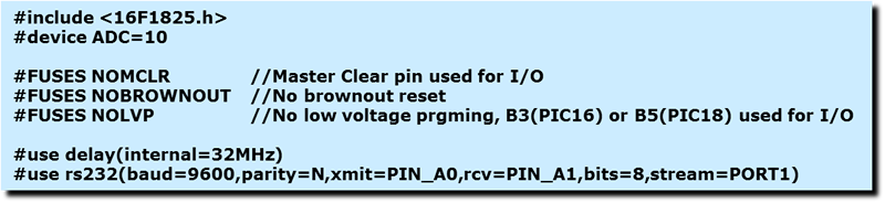
In order to test the generator, the basic setup previously shown in Figure 17 may be used. The PIC 16F1825 (or any other PIC or device with a serial port) should be programmed as follows (example created in C, using CCS C):
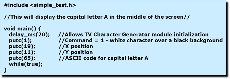 (
(The configuration file (simple_test.h) is this:
 (
(As shown, the connection will be established at the lowest speed (9600), so both S1 and S2 will remain open. A white capital letter A should appear in the middle of a black screen when the program runs.
Firmware driver
Aiming to simplify the programming of the external microcontroller by the user, a firmware driver has been developed in C language (using CCS C program) to be used with Microchip’s PICs. Regardless which platform is used, it should be easily ported by the user to any other environment, and it will serve as an example on how to use all the described commands and byte sequences. Here is a brief description of the Functions implemented, and the full driver is available in the Download section. To use it, simply put this line in the main program: #include<TV_MM.c>.
tv_putc(m,x,y,c)
Displays the character string "c" in the position "x,y". The maximum string length is 40 characters, 1 full line, while "x" can go from 0 to 39, and "y" from 0 to 23. "m" is the image mode, "1" for normal, "2" for inverted. Make sure that the string length plus the "x" position never exceeds 39, the rightmost limit of each line.
Example how to call this function:
char c[41];
c="This is my line of text";
tv_putc(1,5,12,c);
This code will display: This is my line of text at text line 12 ("y"), starting 5 characters from the left ("x"). Since the string contains 23 characters, and "x" is 5, the string reaches position 28, which is OK. In the example, "c" is dimensioned as the maximum string length acceptable here, 40 characters plus null.
tv_put_ascii(m,x,y,a)
Displays the symbol that corresponds to the ASCII code "a"; it also applies for the User Defined Graphics (UDG) located in positions 0 to 31 of the characters' memory. The position on screen is indicated by "x,y", while the mode ("1" - normal, "2" - inverted) is set by "m".
tv_white_pixel(x,y)
Displays a single white pixel in the screen position set by "x,y". In this high resolution mode, "x" can go from 0 to 319 (so "x" is defined as "int16") and "y" from 0 to 191. This command may be used to delete a black pixel in a white background.
tv_black_pixel(x,y)
Displays a single black pixel in the screen position set by "x,y". In this high resolution mode, "x" can go from 0 to 319 (so "x" is defined as "int16") and "y" from 0 to 191. This command may be used to delete a white pixel in a black background.
tv_white_line(x1,y1,x2,y2)
Draws a white line from point "x1,y1" to point "x2,y2". Since "x" ranges from 0 to 319 it is defined as "int16". In case of "y" it may go from 0 to 191. This command may be used to delete a black line in a white background.
tv_black_line(x1,y1,x2,y2)
Draws a black line from point "x1,y1" to point "x2,y2". Since "x" ranges from 0 to 319 it is defined as "int16". In case of "y" it may go from 0 to 191. This command may be used to delete a white line in a black background.
tv_white_box(x1,y1,x2,y2,f)
Draws a white box based on 2 opposite corners, "x1,y1" to "x2,y2". Since "x" ranges from 0 to 319 it is defined as "int16". In case of "y" it may go from 0 to 191. This command may be used to delete a black box in a white background. The box may be empty (f=0) or filled (f=1).
tv_black_box(x1,y1,x2,y2,f)
Draws a black box based on 2 opposite corners, "x1,y1" to "x2,y2". Since "x" ranges from 0 to 319 it is defined as "int16". In case of "y" it may go from 0 to 191. This command may be used to delete a white box in a black background. The box may be empty (f=0) or filled (f=1).
tv_white_circle(x,y,r,f)
Draws a white circle with center "x,y" and radius "r". Since "x" ranges from 0 to 319 it is defined as "int16". In case of "y" it may go from 0 to 191, and "r" from 0 to 95. This command may be used to delete a black circle in a white background. The circle may be empty (f=0) or filled (f=1).
tv_black_circle(x,y,r,f)
Draws a black circle with center "x,y" and radius "r". Since "x" ranges from 0 to 319 it is defined as "int16". In case of "y" it may go from 0 to 191, and "r" from 0 to 95. This command may be used to delete a white circle in a black background. The circle may be empty (f=0) or filled (f=1).
tv_white_ellipse(x,y,a,b,f)
Draws a white ellipse with center "x,y", horizontal radius "a" and vertical radius "b". Since "x" ranges from 0 to 319 it is defined as "int16". In case of "y" it may go from 0 to 191, "a" from 0 to 159 and "b" from 0 to 95. This command may be used to delete a black ellipse in a white background. The ellipse may be empty (f=0) or filled (f=1).
tv_black_ellipse(x,y,a,b,f)
Draws a black ellipse with center "x,y", horizontal radius "a" and vertical radius "b". Since "x" ranges from 0 to 319 it is defined as "int16". In case of "y" it may go from 0 to 191, "a" from 0 to 159 and "b" from 0 to 95. This command may be used to delete a white ellipse in a black background. The ellipse may be empty (f=0) or filled (f=1).
tv_clear_black()
Clears the entire screen, leaving a black background.
tv_clear_white()
Clears the entire screen, leaving a white background.
tv_bright_high()
Sets the entire screen brightness to high level. Useful for viewing in bright environments (e.g. daylight).
tv_bright_low()
Sets the entire screen brightness to low level. Useful for viewing in dark environments (e.g. nighttime).
tv_vertical(v)
Moves the visible screen vertically, according to the contents of "v" which may go from 0 (up) to 20 (down). The default value is 10, which puts the visible screen in the middle of a properly adjusted analog TV set.
tv_horizontal(h)
Moves the visible screen horizontally, according to the contents of "h" which may go from 0 (left) to 4 (right). The default value is 2, which puts the visible screen in the middle of a properly adjusted analog TV set.
tv_udg(p,g0,g1,g2,g3,g4,g5,g6,g7)
Creates an User Defined Graphic (UDG) in the memory position indicated by "p", which may go from 0 to 31. The following values, g0 to g7, represent each one of the 8 bytes that compose an UDG (8x8 square). This UDG can be retrieved later by using the location "p" as the ASCII code.
Appendix A: TV aspect ratios
The term “aspect ratio”, when referring to TV screens, indicates the relationship between width and height. Standard analog TV sets have a 4:3 aspect ratio, meaning that the screen is 4 times wide by 3 times high. New widescreen TVs have a 16:9 aspect ratio, so they are 16 times wide by 9 times high. “Times” here represents any measurement unit. The TV Character Generator has been designed to work well with both aspect ratios, so it has been set between both of them. The actual aspect ratio is 5:3, as shown in Figure A.
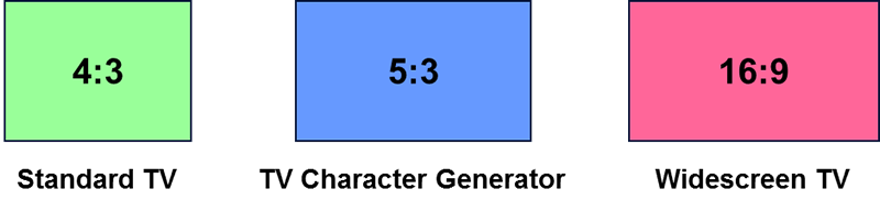
FIGURE A.- TV aspect ratios
The practical implication is that characters and graphics will be seen slightly elongated in the vertical dimension while displayed on a 4:3 TV, and a similar elongation (although much less noticeable) will occur in the horizontal dimension on a 16:9 screen. In both cases, however, the character design has been planned so they can be clearly distinguished.
Appendix B: character map
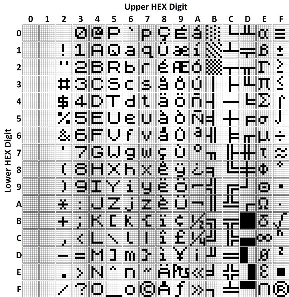
The Character Map shows the 256 available codes that can be called and displayed on screen. The first 32 codes are the UDG. In order to find a character code, just look for the Column and Line headers; e.g. the code for the letter M is 4D hexadecimal, or 77 decimal.