Knowing the precise behavior of a servo, particularly when the datasheet is not available, is fundamental to make sure that the end application will have the expected performance. This is even more relevant nowadays, with the proliferation of all sorts of servos varying in price, quality and performance.
The general definition of servomechanism, or servo, describes a device used to provide control of a desired operation through the use of feedback. In electronics, and particularly when considering electromechanical actuators, a servo is a device that generates a mechanical motion controlled by an electrical pulse.
Examples of such servos can be found in various fields; for the purpose of this description, I will focus the attention on those used in radio-controlled models, since they are extremely popular and widely used, not just for models but for hobbies in general.
There are several types of servos, analog and digital, with plastic or metal gears, with or without ball bearings, etc. However, all share one thing in common: they can be controlled by the same electrical signal, for all practical purposes.
This signal consists of pulses, of variable width, spaced by a fixed period of time (Figure 1).
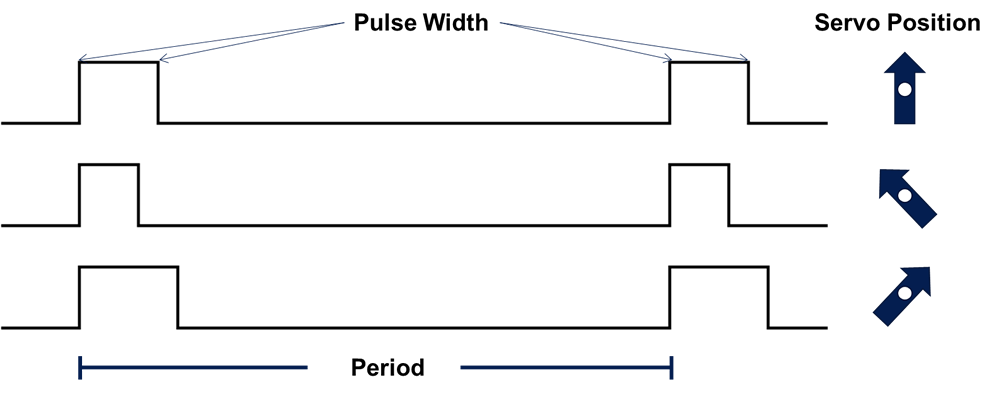 FIGURE 1.- Servo control pulses
The fixed period is usually 20 milliseconds (ms), and the pulse width is what effectively controls the servo rotation. The center position is set at 1,500 microseconds (µs) for most servos, while the extreme positions could reach up to 500 µs on the lower end and 2,500 µs on the upper end. Usually these extremes correspond with the -90 and +90 degrees rotation from the center point at 0. Regarding the direction, it could follow the pulse clockwise or counterclockwise, depending on the manufacturer.
The pulse amplitude, in volts, is usually the same as the servo power supply; the most common supplies are 4.8 V and 6.0 V, although nowadays other amplitudes are possible, from 3.7 V up to 14 V and over.
Why a Servo Tester?
While the manufacturer’s datasheet gives all the specifications of the servo in terms of maximum displacement, speed, dead-band, etc., the datasheet is not always available. And this is particularly true for the wide range of low cost servos currently available in the market. In many cases, although some data may be available, testing the actual performance may give quite different results. At the end of the day, what matters is the actual performance of the servo you will use, not its theoretical behavior.
Making a Servo Tester
A simple servo tester is something very easy to build, and there are plenty of examples on the web. Suffice to say that with a 555 (very popular integrated circuit) and a few other components, you can create an analog tester. However, if you want to measure the servo behavior in a precise way, and with visual indication of the pulse being sent to control it, a slightly more complex approach is required. One step above the simple 555 tester would be one with precise control of the pulse width, including a display showing this value. Cheap versions can be found on the web, but they have one disadvantage: most parameters are already programmed and cannot be changed by the user, such as the minimum step of the control pulse, the maximum and minimum pulses, the frequency of the signal, etc.
Wouldn’t it be great to have a fully Programmable Servo Tester, in which the user has full control of all the parameters to create the desired signal, including manual and automatic testing features?
This is exactly that: a fully Programmable Servo Tester that allows the user control all signal parameters, featuring manual and automatic modes, with a clear and intuitive user interface.
Specifications
The Programmable Servo Tester has the following specifications.
Modes: 4 (Manual, Sweep, Steps, Full).
Minimum pulse width: can be set down to 400 µs.
Maximum pulse width: can be set up to 2,600 µs.
Center position: can be set from 400 µs to 2,600 µs.
Minimum step/pulse resolution: 1 µs.
Maximum step: 250 µs.
Signal period: can be set from 3.0 ms to 50.0 ms.
Repetition cycles (in automatic modes): can be set from 1 to 1000.
Pulse stability/accuracy: crystal controlled.
Power supply: wide range, from 3.7 to 20 V.
Hardware
The full circuit schematic is shown in Figure 2.
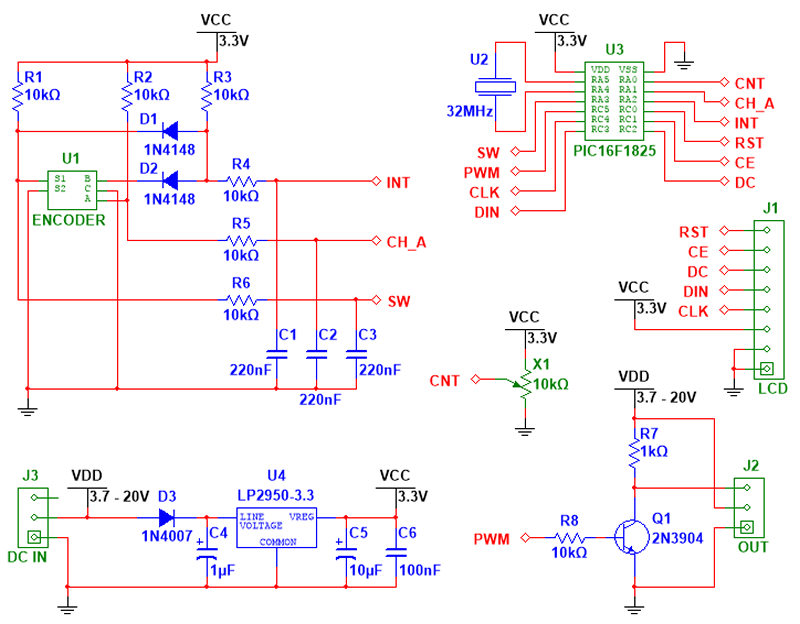
FIGURE 2.- Circuit schematic diagram
The external connections are shown in the lower part; to the left is the power input (J3 – DC IN), which can be connected to the ESC of the RC model, or to any power supply capable of delivering the required current for the servo under test. The unit uses less than 25 mA, so it will not impose a considerable load to the supply. The voltage can be anything from 3.7 to 20 V, depending on the servo requirements.
PLEASE NOTE THAT THE SERVO WILL RECEIVE THE FULL VOLTAGE SUPPLIED BY THE POWER SOURCE, BE CAREFUL NOT TO EXCEED THE SERVO MAXIMUM RATINGS.
To comply with most manufacturers specifications, the center connector is always the +V terminal, while the extremes are GND and SIGNAL. The power input only requires 2 lines, +V and GND, but a 3 terminal connector has been mounted to receive any standard ESC connector. On the right side of the schematic is the servo output (J2 – OUT), with the 3 lines connected (+V, GND and SIGNAL). This will be connected to the servo under test.
The top left shows the user interface, a single encoder with switch (U1). The rotation of the encoder will let the user navigate within the various menus and change the parameters, as well as controlling the servo position in the manual mode. The switch, active when pushing the encoder shaft, will select the marked option, save any parameter after it has been modified, and go back to the main menu from any of the 4 modes (the complete explanation will be given later).
On the top right corner is the microcontroller with the timing crystal at 32 MHz, showing the various connections to the rest of the circuit. Below it, a large connector (J1 – LCD) is the link to the graphic display, where all information will be shown.
Finally, alone in the center of the circuit, a potentiometer (X1) will have the function of adjusting the LCD contrast; all units are adjusted after manufacturing during the quality tests, but this has been included to add more flexibility to the user, so the contrast can be adjusted to any level.
Board layout
The mounted board is shown in Figure 3.
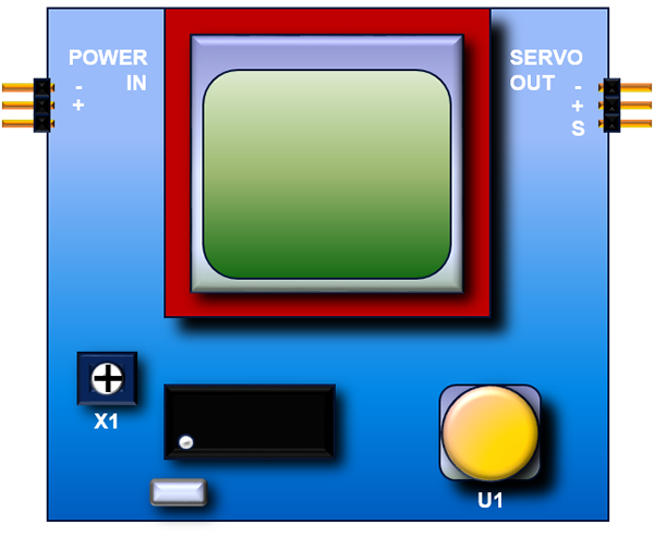
FIGURE 3.- Mounted board layout, showing only the main components
The center top portion of the board is occupied by the LCD sub-board (red). An 84 x 48 pixels monochrome display is used, with a blue backlight (always on). To the left of the display is the power input connector (POWER IN), and to the right is the servo connector (SERVO OUT). The user control is on the bottom right (U1), a rotary encoder with a momentary switch. On the bottom left the potentiometer (X1) adjusts the LCD contrast, mounted next to the microcontroller and the crystal.
The connections are very simple, as previously described, and are depicted in Figure 4.
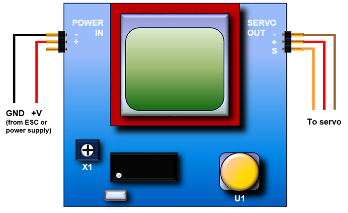
FIGURE 4.- External connections to the board
The color codes used for the servo connections are commonly used by most servo manufacturers, red for power, brown for ground, and orange/yellow for the signal. As previously stated, the +V power is delivered by the center pin, and there is a direct connection between input (POWER IN) and output (SERVO OUT).
Menu and navigation
The options menu is organized in such a way that is both intuitive and easy to navigate. Once power is applied, a welcome screen is briefly presented, and then the program lands in the Main menu (Figure 5).
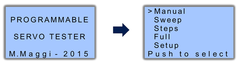
FIGURE 5.- Welcome screen and Main menu
There are 5 options available; a cursor (>) indicates the option currently selected, and the navigation is done by rotating the encoder. Counterclockwise (CCW) moves the cursor down, clockwise (CW) moves it up. Once the desired option is reached, pressing the encoder selects the option, and moves to the corresponding menu, as shown in Figure 6.
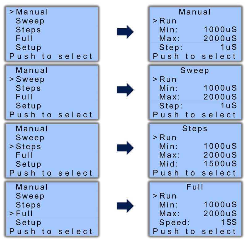
FIGURE 6.- Main menu navigation and selection of the 4 operation modes
These are the 4 operation modes, each one with its submenu. The fifth option is the general Setup, shown in Figure 7.
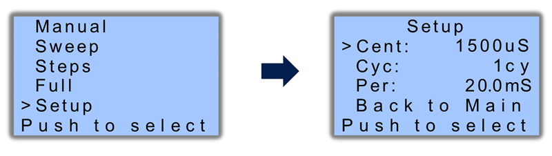
FIGURE 7.- General Setup menu
Let’s review first the Setup menu, and then move to each one of the operation modes.
Setup menu
Here 3 common parameters can be programmed:
Cent (center): defines the center position for the servo. The servo control pulse will have this duration as the default center position. It can be overridden in 3 of the 4 operation modes; however, this will be the final resting position of the servo in the Full Mode. It can go from 400 µs to 2,600 µs, in increments of 1 µs.
Cyc (cycles): defines the number of full cycles the Steps and Full Modes will move the servo before stopping. It is used for reliability and endurance tests, and can go from 1 to 1,000 cycles.
Per (period): defines the period between control pulses. As was previously explained, a servo is controlled by a variable width pulse, repeated over time; this repetition period is usually 20 ms (50 Hz), but modern digital servos may run at higher frequencies. Therefore, there is the option to change this period over a wide range, from 3.0 ms (333 Hz) to 50.0 ms (20 Hz), in increments of 0.1 ms.
Once a particular option is selected with the cursor, and the encoder is pressed, an asterisk (*) next to the value will indicate that it is in programming mode, so it can be changed by rotating the encoder; CW will increase the value, while CCW will decrease it. The bottom legend will change from “Push to select” to “Push to save”. See Figure 8.
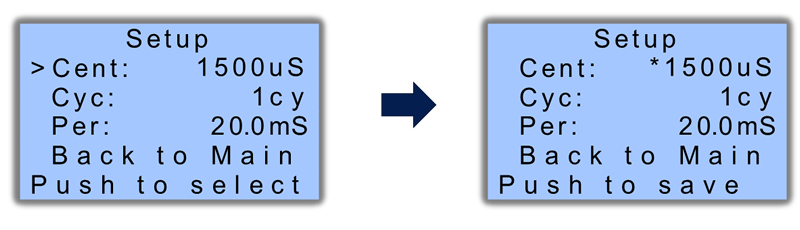
FIGURE 8.- Setup menu and options selection; note the asterisk (*) next to the value to be changed
Once the desired value is reached, a new push to the encoder will save the value to the internal non-volatile memory, and the cursor is shown again next to the option. This is a convenient feature because you do not have to change the values again next time you use the tester with the same configuration, since all your values are saved permanently. The only way to change a value is to select the option again and repeat the procedure with a new value. This is valid for all the configurable parameters of the tester, saving a lot of time when you would like to perform repetitive tests in various servos over different periods of time, using the same values.
With the cursor back in the navigation mode, moving to the last option (“Back to Main”) and pressing the encoder will go back to the Main menu.
Manual menu
This is the first of the 4 operation modes, with 4 options available (Figure 9):
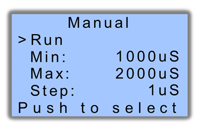
FIGURE 9.- Manual menu options
Run: this option has no values next to it. This is because, when selected by pressing the encoder, this option activates the actual output of the servo signal, and a new screen with the pulse values will be shown. More details will be provided later.
Min (minimum): defines the minimum value of the servo control pulse, so the user cannot produce a pulse shorter than this value. It can go from 400 µs to 2,600 µs, in increments of 1 µs.
Max (maximum): defines the maximum value of the servo control pulse. Similar to the previous, the user cannot produce a pulse longer than this value. The same limits apply.
Step: defines the minimum increment by which, when rotating the encoder during the “Run” menu, the servo control pulse will be changed. It can go from 1 µs to 250 µs, in increments of 1 µs.
Let’s see all these concepts with an example. Let’s assume that “Min” has been set to 700 µs, “Max” to 2,100 µs and “Step” is 10 µs. When “Run” is selected, a new screen appears (Figure 10).

FIGURE 10.- Screen shown in running mode, with the actual pulse width in microseconds (µs)
The large digits show the actual pulse duration in microseconds that is currently being sent to the servo under test. If “Cent” (center, in the Setup menu) was defined as 1,500 µs, this is the value that will be shown on screen. Consequently, the output pulse will be 1,500 µs long, and will be repeated every “Per” (period) milliseconds, as defined in the Setup menu (usually 20.0 ms).
Moving the encoder clockwise (CW), the number will increase, in increments of 10 µs as defined by “Step”. As long as the user keeps rotating the encoder, the value continues to grow (10 µs at a time), as well as the duration of the servo control pulse, which will be identical to the screen value. Once the maximum value is reached, 2,100 µs as defined by “Max”, no further increments are possible, no matter if the user keeps rotating the encoder CW. On the contrary, if the encoder is turned counterclockwise (CCW), the value (and the actual pulse duration) starts to decline, 10 µs at a time, until the minimum is reached, that is 700 µs as defined by “Min”.
If there is a servo connected to the SERVO OUT terminal, the servo arm will follow the changes in the pulse width, moving CW or CCW. Some servos may move in the opposite direction of the encoder rotation, depending on the manufacturer’s criteria, which is normal.
This manual mode is useful to test the servo response to controlled variations, within its full operational range. The “Step” value is quite useful to determine the “dead-band” of the servo, i.e. the minimum pulse variation to which the servo responds. Setting a “Step” value of 1 µs, it is easy to identify how many steps, therefore microseconds, are required to move the arm from one position to the next. Larger “Step” values are used to cover the full range quickly, with few encoder turns.
Once the manual tests are done, pressing the encoder will go back to the Main menu, stopping the pulse output.
Sweep menu
This is the second operation mode, and it is very similar to the Manual Mode (Figure 11).
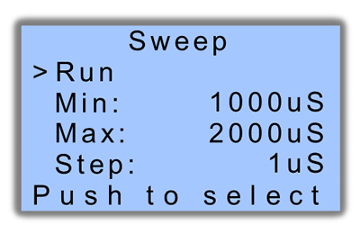
FIGURE 11.- Sweep menu options
The same options are present: “Run”, “Min”, “Max” and “Step”. They have exactly the same functions as before, with the same limits and increment values. However, they are stored separately, so the values saved in the Manual menu can be completely different from the ones saved here.
Once “Run” is selected, the screen with the large numbers is shown, exactly as before. The main difference is that now the numbers, and therefore the servo control pulse, will increment and decrement automatically, moving between “Min” and “Max”, in increments determined by “Step”. This process will continue forever, which is a good way to test the reliability and endurance of a given servo.
The user may stop this process at any time, by pressing the encoder; this will go back to the Main menu and stop the pulse output.
Something to note is that, after this and the previous (Manual) test, the pulse width will retain the last value, when the process was stopped. So the next time any of these modes are called, the pulse will start in the last position, not in the center value.
Steps menu
This third mode is useful to test the servo response by moving it to 3 different positions (Figure 12).
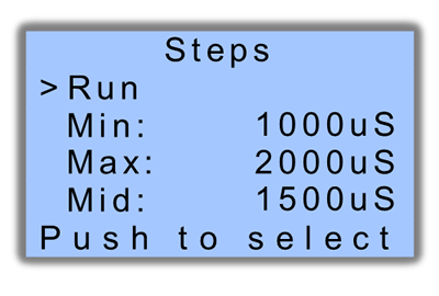
FIGURE 12.- Steps menu options
The options are similar to the previous menus, except the last one:
Mid (middle): defines the middle of the 3 positions the servo arm will reach during this test. It can go from 400 µs to 2,600 µs, in increments of 1 µs.
Please note that all 3 variables have the same range, so eventually “Min” could be set higher than “Max”; it is the user’s responsibility to set these variables correctly. Setting them in an “unnatural” order may cause an unexpected behavior.
Once “Run” is selected, the large digits screen will be shown, and the pulse will follow this sequence: “Mid” - “Max” - “Mid” - “Min” - “Mid”. This is 1 complete cycle. Depending on the number of cycles stored in “Cyc” (cycles, in the Setup menu), this process may run just 1 or up to 1,000 times.
In this mode the servo arm is forced to move quickly between the 3 positions, so it is a good way to test the response of the servo, particularly if large variations are defined.
Once finished, this mode will return automatically to the Main menu, and the last pulse duration will be the one stored in “Mid”. The user may interrupt the process at any time by pressing the encoder.
Full menu
The last of the 4 modes is the most demanding for the servo. It will move the arm between 2 positions (“Min” and “Max”), at a selectable speed (Figure 13).
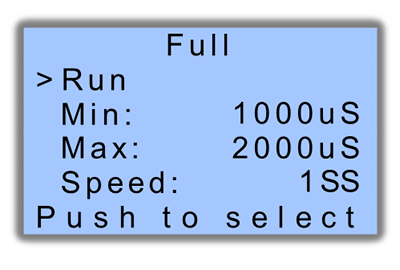
FIGURE 13.- Full menu options
The first 3 options are already well known; the last one deserves an explanation:
Speed: defines the speed at which the change of pulse values will occur, therefore, the speed at which the servo is expected to respond. It may go from 1 sweep per second (SS) to 10 SS. A sweep means a change from one of the values to the other, e.g. moving from 1,000 µs to 2,000 µs. At low speed, this change will happen once per second; at the highest speed, this will occur ten times per second.
The variable “Cyc” (cycles, in the Setup menu) determines how many full cycles there are in each run (1 to 1,000); after this, the process returns to the Main menu. The final pulse value will be determined by “Cent” (center, in the Setup menu), as explained before. Again, the user may interrupt the process at any time by pressing the encoder.
A final note: as previously mentioned, the potentiometer X1 may be used to adjust the LCD contrast. This feature is available in all menus except when running, i.e. when the screen with the large numbers is being shown. This is intentional, in order not to interfere with the pulse generation.
The unit is provided without an external enclosure; however the board has 4 mounting holes, one in each corner, in case the user decides to attach it to a customized setup.
This concludes the explanation of the full functionality of the Programmable Servo Tester; the flexibility provided by the several adjustable variables, added to the precision of a crystal-controlled timing, makes this a suitable tool to test almost any servo available in the market.