The screwdriver is an essential tool in any workshop; dealing with electronics, small screwdrivers with multiple interchangeable bits are required to assemble / disassemble the units or the components inside. Usually no much torque is required to perform these operations, since it is not heavy duty equipment.
With the increased availability of high capacity lithium-ion batteries in different sizes, many rotary tools have become cordless and rechargeable, and this applies to screwdrivers as well. There are currently several products in the market under the name of “electric screwdriver”, as well as many videos posted by DIY enthusiasts showing how to build your own electric screwdriver.
While many of the proposals look good in theory, when you try to replicate them you find that you do not have the information of all the components required, the electrical connections are not clear, or there are safety risks, e.g. when connecting unprotected batteries directly to the motor.
Here we will review the design and construction of a rechargeable electric screwdriver, step by step, with the following characteristics:
- All components are widely available in the market, are standard and affordable.
- The unique parts, such as body, trigger and bit adapter, are 3D printed.
- The design will accept an 18650 lithium-ion battery, either protected or unprotected.
- The charge and protection modules are integrated in one board, with a micro USB interface.
- The unit will incorporate a 12-volt boost converter, so the motor speed / torque is constant.
- A main switch will disconnect the battery from the boost converter while not in use.
- A pivoting trigger mechanism will allow clockwise and counterclockwise rotation.
- A 12-volt geared motor with a high reduction ratio will generate high torque.
- The bit adapter will accommodate 4 mm hexagonal bits, featuring a magnetic lock.
- Dual ball bearing design will prevent wobble and eliminate stress on the motor gears.
- Two white LEDs in the front will keep the working area illuminated.
- The overall design as well as the switches location will be ergonomic and comfortable to use.
With these guidelines in mind, let’s start building the screwdriver.
Required parts
As previously indicated, all parts are widely available as of July 2020. Figure 1 shows an overview of the complete screwdriver with all the parts in place, with the exception of the left body cover, the screws, 2 resistors (for the LEDs) and the wiring:
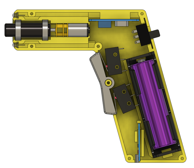
FIGURE 1. – Screwdriver overview
This is the full parts list (the links are just for reference, you may find them somewhere else):
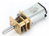
- N20 geared motor, 12 volts, 100 RPM (any value from 100 to 200 RPM will work as well).
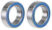
- Ball bearings (2): internal diameter 10 mm, external diameter 15 mm, width 4 mm.

- Neodymium magnet, cylinder 6mm diameter, height 3mm.
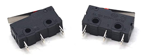
- Limit switches (2), with “Normally Open” and “Normally Closed” terminals.
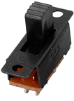
- Slide switch (DPDT) with 2 positions and 6 terminals.
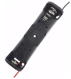
- 18650 battery holder.
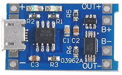
- Lithium-ion battery charger/protector module TP4056.
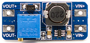
- Boost converter MT3608 (adjustable output voltage, up to 2 amperes current capacity).
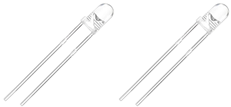
- White 3 mm LEDs (2).
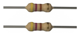
- Resistors (2), 470 Ω, 1/8 watt.
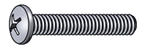
- Screws:
- Philips Pan Head #2-56 x 3/8 (quantity: 4).
- Philips Pan Head #2-56 x 1/2 (quantity: 3).
- Philips Pan Head #2-56 x 3/4 (quantity: 4).
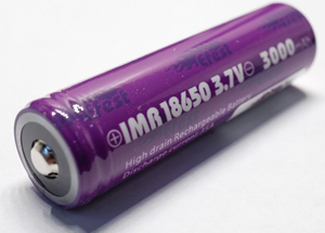
- Battery: 18650 (button top, protected or unprotected).
- 3D printed parts (STL files included in the Download section):
- Body (right and left covers).
- Trigger.
- Bit adapter.
- Miscellaneous:
- Wires (stranded and solid, 22-24 AWG).
- Thin wire for LED connections.
- Soldering iron and solder.
Printing the parts
All parts can be printed with no supports if properly placed on a flat face. For the body (right and left covers) a layer height of 0.2 mm is adequate; the trigger can be printed at a layer height of 0.1 mm or less, so it feels smooth to the touch. All of them are printed in regular PLA (Figure 2).
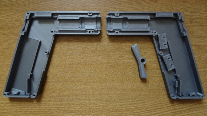
FIGURE 2. – Main 3D printed parts
The bit adapter requires additional considerations since it will have a magnet embedded inside. The part is basically a cylinder with D-shaped hole on one end (to match the motor shaft) and a hexagonal hole on the other (to match the bits). In the middle there is a cavity for the magnet (Figure 3).
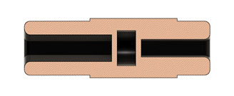
FIGURE 3. – Internal view of the bit adapter; the middle cavity will house the magnet
The process to embed an object into a 3D printed part requires the printer to pause at a certain layer so the user can put the object, then resume printing. Many slicers will have this option included as a Post Processing Script. In CURA, this script is “Pause at Height”; I am using a 0.08 mm layer height, so I ask the printer to pause at layer 210, and move the head out of the way (Figure 4).
Once the printer reaches that layer it moves the head to coordinates X=20, Y=20, so there is no obstruction to place the magnet inside the cavity. There is no need to put any glue; once the printing job resumes, a layer of plastic will cover the magnet. The neodymium magnet is strong enough to keep the bits in place while using them.
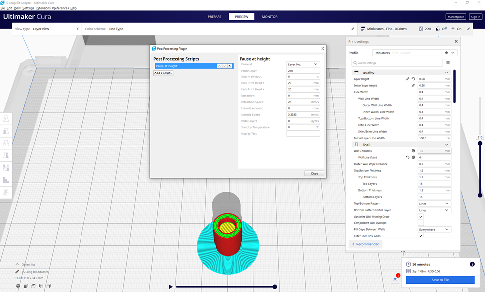
FIGURE 4. – CURA’s Post Processing Script to “Pause at Height”
If this process is too complicated, or you do not feel comfortable doing it, the bit adapter can also be printed normally, without pausing; there will not be a magnetic lock for the bit, but it will remain in place by friction. The bit side receptacle is 16 mm deep.
You may notice that the bit adapter does not have a constant outside diameter: it starts at 10mm then expands to 11mm, to finally go back to 10mm. This will lock the ball bearings in place, which will prevent any external longitudinal force to damage the motor gears.
This part should be able to withstand rotational forces, so it is recommended to print it with a material stronger than normal PLA; I am using PLA+ (from eSun) with good results.
Assembling the components
All components will be mounted on the right cover, as show in Figure 5. Both covers are similar, but not identical. They have been designed to keep the parts in place with no need to add any glue or adhesive tape.
It is recommended to position all the parts first, before wiring them. In this way, you can properly measure the wire length required for each connection. The space for the wires has been considered in the design, but a careful planning will make the final mounting process much easier, clean and safe.
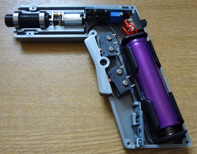
FIGURE 5. – Components mounted on the right cover (the boost converter is rotated 180 degrees in this picture)
To mount the motor, bit adapter and ball bearings, just slide the bearings into the adapter and then insert the motor shaft in the corresponding end. The process is straight-forward. The printed body has grooves for the bearings and a cavity for the motor and gears; the fit is precise so there is no play that could compromise the proper screwdriver operation (Figure 6).
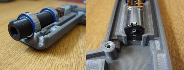
FIGURE 6. – Bearings, adapter and motor in place
The limit switches will be mounted in place with 2 screws each; their position needs to match the trigger reach, so there is some room for adjustment. Figure 7 shows the correct alignment of the limit switches and the trigger.
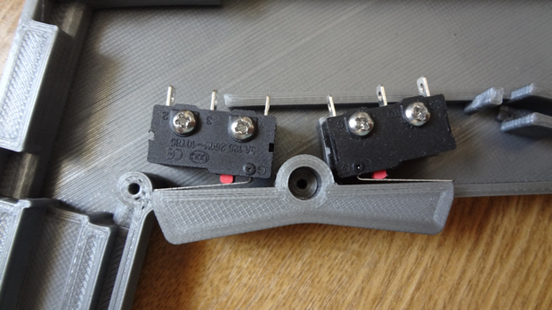
FIGURE 7. – Switches and trigger; the metal lever just touches the trigger
The screws for the switches are #2-56 x 3/8. They are slightly smaller than the diameter of the holes in the switches, so there is room for adjustment. With both switches and the trigger in place move them until the metal levers just touch the trigger at both ends; this guarantees the maximum movement without leaving the trigger loose. Once this is done, tighten the 4 screws.
The trigger should feel secure in place but soft to the touch, and there should be a distinctive clicking sound when each switch is activated. The spring action of the switch is enough to return the trigger back to the rest position when released; if not, light sanding of the trigger axle will help.
The main switch in the back just slides into place, no screws required; the grooves in the wall will keep it secure (Figure 8).
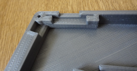
FIGURE 8. – Main switch location
The same applies for the charging / protection module TP4056; it should fit between the plastic walls and the groove in the body (Figure 9).
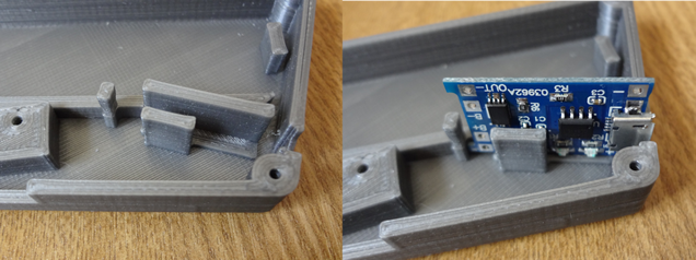
FIGURE 9. – TP4056 module installation
The micro USB port will be accessible from the outside; when both covers are closed together, the hole will have the shape of the port (Figure 10).
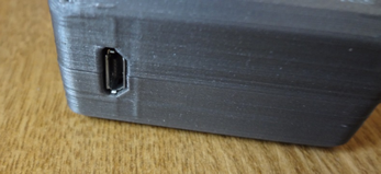
FIGURE 10. – Micro USB port
The battery holder has guides in the form of low walls to keep it in place (Figure 11).
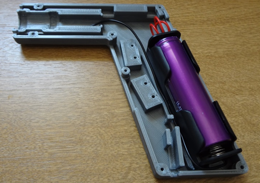
FIGURE 11. – Battery holder with battery
This holder does not require any additional adhesive to remain secure in place; with the battery in, the other cover will apply the right amount of pressure to prevent them from moving. In addition, the left cover has a wide groove where the battery touches it, calculated at the right distance to make it a tight fit (Figure 12).
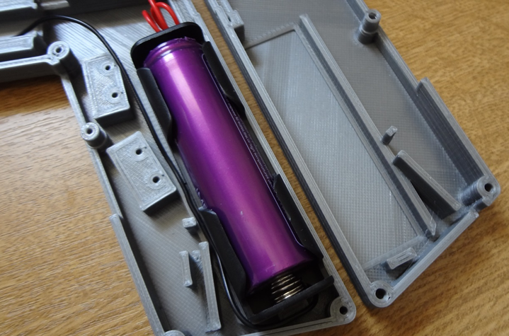
FIGURE 12. – Right and left covers; the wide groove for the battery is seen in the left cover (right side of the image)
The boost converter MT3608 does not have a specific support structure, but will be held in place when the wiring is done; solid wires from the main switch will support one side, while the opposite is kept in place by a pillar behind the motor (Figure 13).
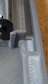
FIGURE 13. – Pillar keeping the MT3608 module in place
Finally, the LEDs have their own hole, with a groove to fit the base ring and keep them in place (Figure 14).
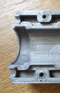
FIGURE 14. – Holes for the LEDs, at each side of the front bearing groove
With the components in place, it is time to plan the wiring; once the proper lengths have been measured and cut, some components may be removed to make the soldering process easier. Do not unscrew the limit switches if you already adjusted them; they can be soldered in place.
Electric Diagram
The connections are relatively simple:
- The TP4056 module (charger / protector) connects to the battery via the B+ and B- terminals (to the positive and negative ends respectively).
- This module also connects to the main switch via the OUT+ and OUT- terminals. These two go to the middle pins of the main switch.
- The pins on one end of the switch connect to the MT3608 module, the positive to the VIN+ terminal, and the negative to the VIN-terminal; pay special attention to the polarity. The remaining two pins of the switch are not connected.
- At this point, test the connections and adjust the blue potentiometer in the MT3608 until there are 12 volts between VOUT+ and VOUT-.
- Now connect the positive output of the MT3608 (VOUT+) to the Normally Open (NO) pin of each limit switch (middle pin).
- The negative output (VOUT-) goes to the Normally Closed (NC) pin of each limit switch.
- The Common (C) pins of the switches connect to the motor terminals (one each).
- Finally, the LEDs are connected to VOUT+ (long pin) and VOUT- (short pin, through a 470 Ω resistor to limit the current).
The full electric diagram is shown in Figure 15.
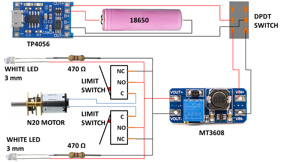
FIGURE 15. – Electric diagram
The wiring from the main switch to the MT3608 module should be made with short solid wire to provide support to the module board; the wiring to the LEDs is made with thin wire to fit the grooves in each side of the motor and spindle mechanism.
Depending on how you connect the wires to the motor, the upper limit switch will trigger a clockwise or counterclockwise rotation, while the lower will do the opposite. It is up to you which one you prefer to connect to be the screw or unscrew button.
This circuit is configured so the LEDs are ON as soon as the main switch is ON; this is different from many screwdrivers, where the light goes ON only when you press the rotation buttons. I prefer the way I wired it for three reasons:
- I want the area illuminated even before I start turning the screw, so I can see it.
- The LEDs serve as an indicator that the main switch is ON, therefore consuming power.
- It is much easier this way.
You may wonder why the main switch is required. The boost converter draws power from the battery even if the motor is not running, so it needs to be disconnected when not in use. In addition, it is always recommended to have any load disconnected from the battery while it is being charged, so the TP4056 can properly sense the charge current and avoid overcharging.
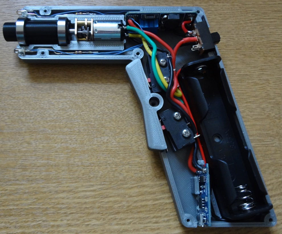
FIGURE 16. – Finished unit, with all components and wires connected
Once all the wiring is done, the unit should look like Figure 16. Make sure that no wire crosses on top of an internal wall that may have a counterpart on the other half of the body.
The final touch is to close the unit. Carefully position the left cover and slowly join them together. It should be a perfect fit, provided all components are in place and no wires are blocking any contact wall. The battery holder may require a gentle push from the negative end with a small object (e.g. a flat screwdriver) to clear one the limiting inner walls.
Once the unit is closed and there are no gaps, put the external screws. There are different sizes, so please refer to Figure 17 for the proper screw location.
The screws should be tight but make sure not to overtighten them, to prevent damaging the plastic. The screw that goes through the pivot point of the trigger may require unscrewing one or two turns from the end point, so the trigger can move freely. You may have to experiment to find the right spot.
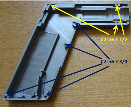
FIGURE 17. – External screws location
The unit is now ready to be used! Just insert any hexagonal 4 mm bit from a cheap manual set.
When it is time to charge the battery, just turn the main switch off and plug the unit to any available USB port. The red LED on the TP4056 will light while the battery is charging; when charged, the blue LED will turn on. There are no holes in the unit to see the LEDs; however, the right cover has a rectangle that is thinner than the rest of the wall so the LEDs are visible (Figure 18).
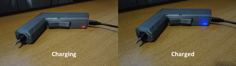
FIGURE 18. – Red and blue LEDs indicate the charging progress
A note about speed, torque and overcurrent protection:
This unit, as most small-sized electric screwdrivers, has been designed to perform precise tasks which do not demand high power. However, the use of an N20 motor with a high reduction ratio provides a reasonable amount of torque, sacrificing speed. At the beginning I mentioned that any speed from 100 to 200 RPM will work; while this is true, higher speed means less torque, keeping the same configuration and power source. Below 100 RPM it would be too slow to be practical; above 200 RPM, too weak. To me, 100 RPM is a good compromise, and I have had no problems with torque.
In situations that the torque required is too high, the unit may stall; this will create an excess of current going to the motor, and may trigger the TP4056 overcurrent protection. If that happens, turn the main switch off and on again to resume operation.
I would not recommend bypassing the TP4056 overcurrent protection, unless you are using a protected battery; if that is the case, connect the negative wire that goes from the TP4056 to the main switch to B- instead of OUT-. The TP4056 will no longer protect the battery against overcurrent and over discharge, and you will rely solely on the internal protection that comes with the battery.